Toyota Tacoma (2015-2018) Service Manual: Components
COMPONENTS
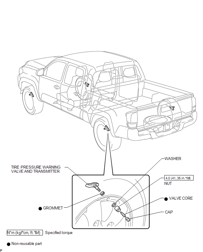
ILLUSTRATION

 Disposal
DISPOSAL
CAUTION / NOTICE / HINT
HINT:
The tire pressure warning valve and transmitter is powered by a lithium battery.
When disposing of the tire pressure warning valve and transmitter, remove t ...
Other materials:
Parts Location
PARTS LOCATION
ILLUSTRATION
*A
for Automatic Transmission
-
-
*1
FRONT SPEED SENSOR LH
*2
FRONT SPEED SENSOR RH
*3
FRONT AXLE WITH ABS ROTOR BEARING ASSEMBLY LH
- FRONT SP ...
Steering Pad Switch
Components
COMPONENTS
ILLUSTRATION
Removal
REMOVAL
PROCEDURE
1. REMOVE STEERING PAD
(See page
)
2. REMOVE STEERING PAD SWITCH ASSEMBLY
(a) Disconnect the 2 connectors.
(b) Disengage the 2 clamps.
(c) Remove the 4 screws.
...
Pre-collision System Warning Buzzer
Components
COMPONENTS
ILLUSTRATION
*1
SKID CONTROL BUZZER
-
-
Inspection
INSPECTION
PROCEDURE
1. INSPECT SKID CONTROL BUZZER
(a) Make sure that there is no looseness in the locking part and connecting
part of the conne ...
