Toyota Tacoma (2015-2018) Service Manual: Components
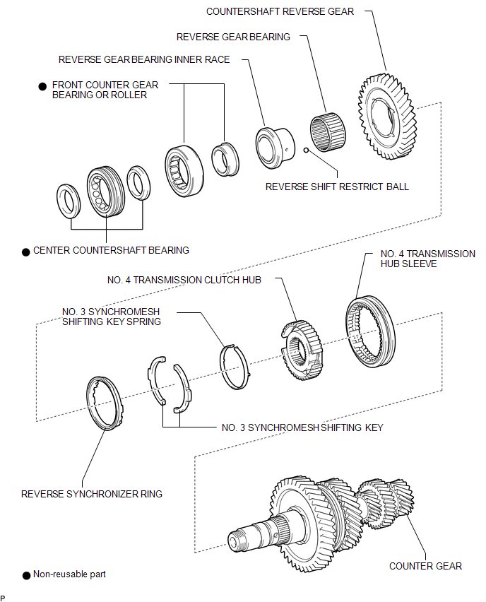
COMPONENTS
ILLUSTRATION
ILLUSTRATION
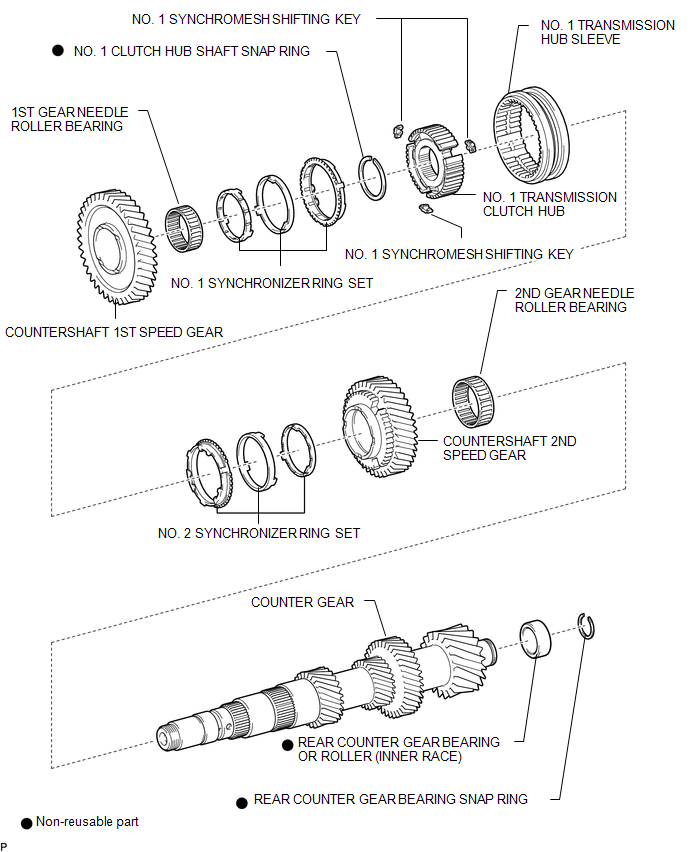
 Counter Gear
...
 Disassembly
DISASSEMBLY
PROCEDURE
1. INSPECT COUNTERSHAFT REVERSE GEAR THRUST CLEARANCE
(a) Using a dial indicator, measure the countershaft reverse gear thrust
clearance.
Standard clearance: ...
Other materials:
Removal
REMOVAL
PROCEDURE
1. REMOVE NO. 1 ENGINE UNDER COVER SUB-ASSEMBLY
2. REMOVE FRONT EXHAUST PIPE ASSEMBLY
(See page )
3. REMOVE NO. 1 OIL COOLER INLET TUBE AND NO. 1 OIL COOLER OUTLET TUBE
NOTICE:
When disconnecting the hoses from the tube, support the tube by hand and be careful
to prevent ...
4WD Control Switch Circuit
WIRING DIAGRAM
PROCEDURE
1.
CONFIRM PROBLEM SYMPTOM
(a) Confirm the problem symptoms.
Result
Result
Proceed to
The 4WD indicator light (green) and 4LO indicator light remain off
A
The 4WD indica ...
Removal
REMOVAL
PROCEDURE
1. PRECAUTION
NOTICE:
After turning the ignition switch off, waiting time may be required before disconnecting
the cable from the negative (-) battery terminal.
Therefore, make sure to read the disconnecting the cable from the negative (-)
battery terminal notices before p ...
