Toyota Tacoma (2015-2018) Service Manual: Components
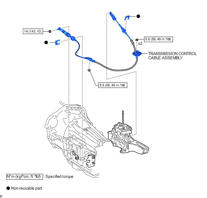
COMPONENTS
ILLUSTRATION

 Adjustment
ADJUSTMENT
PROCEDURE
1. REMOVE FRONT CONSOLE BOX
(See page )
2. ADJUST TRANSMISSION CONTROL CABLE ASSEMBLY
(a) Move the shift lever to N.
(b) Disconnect the end of the transmission control cab ...
Other materials:
On-vehicle Inspection
ON-VEHICLE INSPECTION
PROCEDURE
1. INSPECT DRIVER SEAT BELT WARNING LIGHT
HINT:
The seat belt warning light on the combination meter assembly is used for both
the driver seat and front passenger seat.
(a) Turn the ignition switch to ON.
(b) When the driver seat belt is not fastened, check th ...
Installation
INSTALLATION
PROCEDURE
1. INSTALL TRANSMISSION WIRE
(a) Coat 2 new O-rings with ATF, and install them to the 2 temperature sensors.
(b) Coat a new O-ring with ATF, and install it to the transmission wire.
(c) Install the transmission wire to the automatic transmission case sub-assembly
with t ...
Disassembly
DISASSEMBLY
PROCEDURE
1. INSPECT COUNTERSHAFT REVERSE GEAR THRUST CLEARANCE
(a) Using a dial indicator, measure the countershaft reverse gear thrust
clearance.
Standard clearance:
0.150 to 0.300 mm (0.0060 to 0.0118 in.)
If the clearance is outside the specification, repl ...
