Toyota Tacoma (2015-2018) Service Manual: Adjustment
ADJUSTMENT
PROCEDURE
1. REMOVE FRONT CONSOLE BOX
(See page .gif) )
)
2. ADJUST TRANSMISSION CONTROL CABLE ASSEMBLY
(a) Move the shift lever to N.
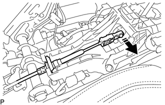
(b) Disconnect the end of the transmission control cable assembly from the transmission floor shift assembly.
 Text in Illustration
.png) |
Disconnect in this Direction |
|
(c) Push the 2 claws together at the top of the transmission control cable lock piece. While holding the 2 claws together, push the 2 lugs on the bottom of the lock piece toward each other and upward to pull out the lock piece. Text in Illustration
|
|
.png)
(d) Connect the end of the transmission control cable assembly to the transmission floor shift assembly.
.png) Text in Illustration
Text in Illustration
|
*1 |
Lock Piece |
|
|
Connect in this Direction |
NOTICE:
- Check that the park/neutral position switch and shift lever are in N.
- Make sure that the lock piece is pulled up.
- Push on the end of the cable all the way to the base of the transmission floor shift assembly pin.
|
(e) Push the lock piece into the adjuster case. Text in Illustration
NOTICE: Securely push in the lock piece until it locks. |
|
.png)
(f) After adjusting the shift lever position, check the operation and function of the shift lever. If there is a problem, adjust the position again.
3. INSTALL FRONT CONSOLE BOX
(See page )
 Components
COMPONENTS
ILLUSTRATION
...
 Installation
INSTALLATION
PROCEDURE
1. INSTALL TRANSMISSION CONTROL CABLE ASSEMBLY
(a) Install the transmission control cable assembly from outside the vehicle
body and attach the 3 claws of the cable retaine ...
Other materials:
Clutch Pedal Switch
On-vehicle Inspection
ON-VEHICLE INSPECTION
PROCEDURE
1. CHECK CLUTCH START SYSTEM
(a) Check that the engine does not start when the clutch pedal is released.
(b) Check that the engine starts when the clutch pedal is fully depressed.
If necessary, replace the clutch start switch assembly.
...
Open Circuit in IG1/IG2 Power Source Circuit (C1242)
DESCRIPTION
If there is a problem with the skid control ECU (master cylinder solenoid) power
supply circuit, the skid control ECU outputs the DTC and prohibits operation under
the fail safe function.
If the voltage supplied to terminal IG1 and/or IG2 is not within the DTC detection
threshold ...
Precaution
PRECAUTION
1. IGNITION SWITCH EXPRESSION
(a) The type of ignition switch used on this model differs depending on the specifications
of the vehicle.
The expressions listed in the table below are used in this section.
Expression
Ignition Switch (Position)
Engine ...
