Toyota Tacoma (2015-2018) Service Manual: Clutch Start Cancel Switch
Inspection
INSPECTION
PROCEDURE
1. INSPECT CLUTCH START CANCEL SWITCH ASSEMBLY
|
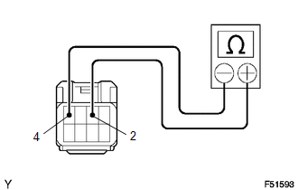
(a) Using an ohmmeter, check that there is resistance between terminals 2 and 4. Standard: 10 kΩ or higher If the result is not as specified, replace the clutch start cancel switch. |
|
|
(b) Connect the positive (+) lead from the battery to terminal 3 and connect negative (-) lead to terminal 1. |
|
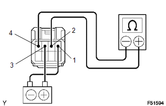
(c) Using an ohmmeter, check that there is resistance between terminals 2 and 4.
Standard:
10 kΩ or higher
If the result is not as specified, replace the clutch start cancel switch.
|
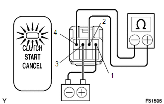
(d) Check that the indicator light comes on and there is resistance between terminals 2 and 4 when the switch is pressed. Standard: Below 1 Ω If the result is not as specified, replace the clutch start cancel switch. |
|
|
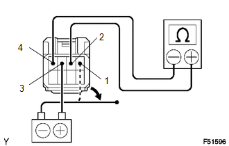
(e) Using an ohmmeter, check that there is resistance between terminals 2 and 4 when the battery lead is disconnected. Standard: 10 kΩ or higher If the result is not as specified, replace the clutch start cancel switch. |
|
 Clutch Release Cylinder(for Rc62f)
Components
COMPONENTS
ILLUSTRATION
Disassembly
DISASSEMBLY
PROCEDURE
1. REMOVE CLUTCH RELEASE CYLINDER KIT
(a) Remove the boot from the cylinder body.
(b) Remove the push rod from the bo ...
 Clutch System
...
Other materials:
Diagnosis System
DIAGNOSIS SYSTEM
1. CHECK DLC3
(a) Check the DLC3 (See page ).
2. INSPECT BATTERY VOLTAGE
(a) Measure the battery voltage.
Standard Voltage:
11 to 14 V
If the voltage is below 11 V, recharge or replace the battery.
3. SELF-DIAGNOSTIC MODE (OPERATING IGNITION KEY CYLINDER)
(a) Switch to se ...
Terminals Of Ecu
TERMINALS OF ECU
1. TERMINALS OF ECU
Text in Illustration
*a
Component without harness connected
(Skid Control ECU (Master Cylinder Solenoid))
-
-
Terminal No. (Symbol)
Terminal Description
S1-1 (GND1 ...
Side Airbag Sensor RH Circuit Malfunction (B1620/21)
DESCRIPTION
The side airbag sensor assembly RH consists of parts such as the safing sensor,
the diagnostic circuit and the lateral deceleration sensor.
When the airbag sensor assembly receives signals from the lateral deceleration
sensor, it determines whether or not the SRS should be activate ...
