Toyota Tacoma (2015-2018) Service Manual: Clearance Warning Buzzer Circuit
DESCRIPTION
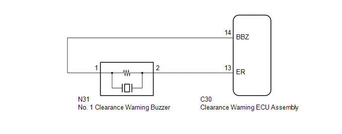
This circuit consists of the No. 1 clearance warning buzzer and clearance warning ECU assembly. An ECU-excited type buzzer is used. The battery voltage supplied through the buzzer is grounded inside the clearance warning ECU assembly using a pulsed digital pattern, producing sound. The ECU operates the buzzer using a sound pattern that changes depending on the distance to the obstacle.
WIRING DIAGRAM
PROCEDURE
|
1. |
PERFORM ACTIVE TEST USING TECHSTREAM |
(a) Connect the Techstream to the DLC3.
(b) Turn the ignition switch to ON.
(c) Turn the Techstream on.
(d) Enter the following menus: Body Electrical / Intuitive P/A / Active Test.
(e) Check that the buzzer operates by performing the Active Test.
Intuitive P/A|
Tester Display |
Test Part |
Control Range |
Diagnostic Note |
|---|---|---|---|
|
Buzzer |
No. 1 clearance warning buzzer |
Operate or Stop |
Confirm that the vehicle is stopped and the ignition switch is ON |
OK:
The No. 1 clearance warning buzzer sounds.
| OK | .gif) |
PROCEED TO NEXT SUSPECTED AREA SHOWN IN PROBLEM SYMPTOMS TABLE |
|
.gif)
|
2. |
CHECK HARNESS AND CONNECTOR (CLEARANCE WARNING ECU ASSEMBLY - NO. 1 CLEARANCE WARNING BUZZER) |
(a) Disconnect the N31 connector from the No. 1 clearance warning buzzer.
(b) Disconnect the C30 connector from the clearance warning ECU assembly.
(c) Measure the resistance according to the value(s) in the table below.
Standard Resistance:
|
Tester Connection |
Condition |
Specified Condition |
|---|---|---|
|
C30-14 (BBZ) - N31-1 |
Always |
Below 1 Ω |
|
C30-13 (ER) - N31-2 |
||
|
C30-14 (BBZ) - Body ground |
10 kΩ or higher |
|
|
C30-13 (ER) - Body ground |
| NG | |
REPAIR OR REPLACE HARNESS OR CONNECTOR |
|
|
3. |
REPLACE NO. 1 CLEARANCE WARNING BUZZER |
(a) Replace the No. 1 clearance warning buzzer with a new or known good one (See
page .gif) ).
).
|
|
4. |
PERFORM ACTIVE TEST USING TECHSTREAM |
(a) Connect the Techstream to the DLC3.
(b) Turn the ignition switch to ON.
(c) Turn the Techstream on.
(d) Enter the following menus: Body Electrical / Intuitive P/A / Active Test.
(e) Check that the buzzer operates by performing the Active Test.
Intuitive P/A|
Tester Display |
Test Part |
Control Range |
Diagnostic Note |
|---|---|---|---|
|
Buzzer |
No. 1 clearance warning buzzer |
Operate or Stop |
Confirm that the vehicle is stopped and the ignition switch is ON |
OK:
The No. 1 clearance warning buzzer sounds.
| OK | |
END (NO. 1 CLEARANCE WARNING BUZZER WAS DEFECTIVE) |
| NG | |
REPLACE CLEARANCE WARNING ECU ASSEMBLY |
 Clearance Sonar Main Switch Circuit
DESCRIPTION
The back sonar or clearance sonar switch assembly is installed at the base of
the driver side of the instrument panel.
When the back sonar or clearance sonar switch assembly is turned ...
 Clearance Warning ECU Power Source Circuit
DESCRIPTION
This circuit provides power to operate the clearance warning ECU assembly.
WIRING DIAGRAM
CAUTION / NOTICE / HINT
NOTICE:
Inspect the fuse for circuits related to this system before ...
Other materials:
If the vehicle becomes stuck
Carry out the following procedures if the tires spin or the vehicle becomes
stuck in mud, dirt, or snow.
Stop the engine. Set the parking
brake and put the shift lever in P (vehicles with an automatic transmission) or
N (vehicles with a manual transmission).
Remove the mud, snow, or sand f ...
Differential Oil
Adjustment
ADJUSTMENT
PROCEDURE
1. INSPECT DIFFERENTIAL OIL
(a) Stop the vehicle on a level place.
(b) Remove the differential filler plug and gasket.
(c) Check that the oil level is within 5 mm (0 to 0.20 in.) of the bottom of
the filler plug opening.
NOTICE:
Excessively large ...
Installation
INSTALLATION
PROCEDURE
1. INSTALL REAR NO. 2 POWER WINDOW REGULATOR SWITCH ASSEMBLY
(a) Engage the 2 claws to install the rear No. 2 power window regulator switch
assembly.
2. INSTALL INSTRUMENT PANEL LOWER CENTER FINISH PANEL
Click here
3. INSTALL NO. 2 INSTRUMENT PANEL GARNISH SUB-ASSEMB ...
