Toyota Tacoma (2015-2018) Service Manual: Camshaft
Components
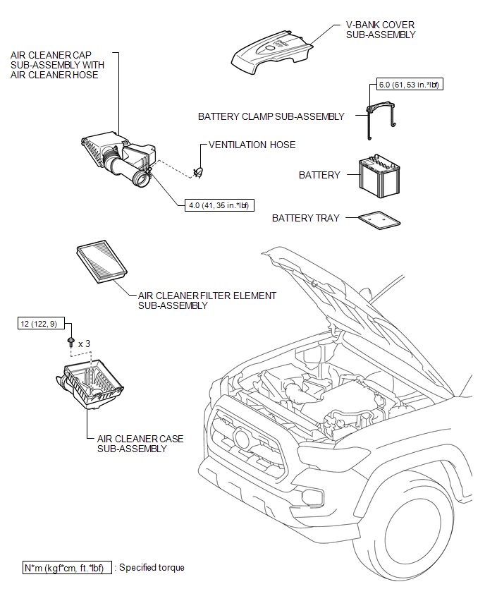
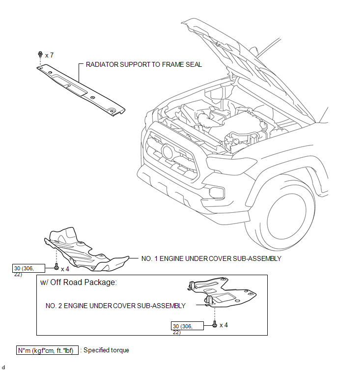
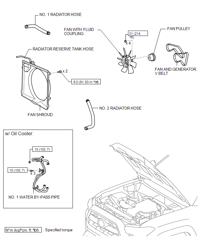
COMPONENTS
ILLUSTRATION
ILLUSTRATION
ILLUSTRATION
ILLUSTRATION
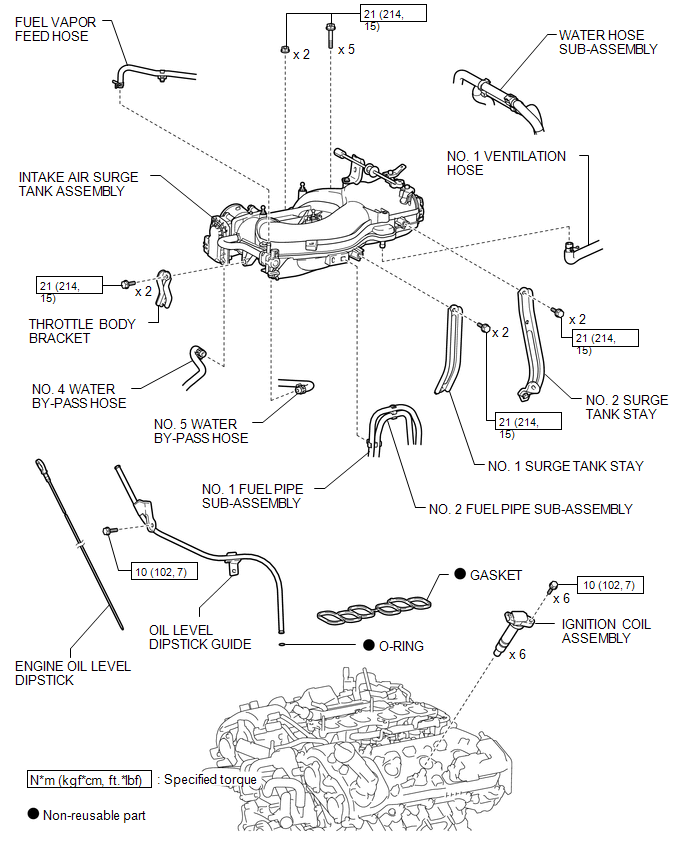
ILLUSTRATION
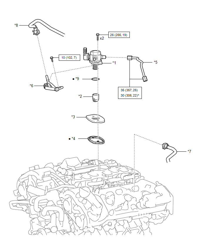
|
*1 |
FUEL PUMP ASSEMBLY |
*2 |
FUEL PUMP LIFTER ASSEMBLY |
|
*3 |
FUEL PUMP LIFTER GUIDE |
*4 |
FUEL PUMP SPACER GASKET |
|
*5 |
NO. 1 FUEL PIPE SUB-ASSEMBLY |
*6 |
FUEL TUBE SUB-ASSEMBLY |
|
*7 |
NO. 1 FUEL TUBE SUB-ASSEMBLY |
*8 |
NO. 2 FUEL TUBE SUB-ASSEMBLY |
|
*9 |
O-RING |
- |
- |
.png) |
N*m (kgf*cm, ft.*lbf): Specified torque |
* |
For use with union nut wrench |
|
â—Ź |
Non-reusable part |
- |
- |
ILLUSTRATION
ILLUSTRATION
ILLUSTRATION
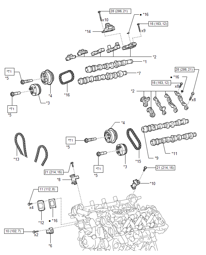
|
*1 |
CAMSHAFT |
*2 |
CAMSHAFT BEARING CAP |
|
*3 |
CAMSHAFT TIMING EXHAUST GEAR ASSEMBLY |
*4 |
CAMSHAFT TIMING GEAR ASSEMBLY |
|
*5 |
CAMSHAFT TIMING GEAR BOLT |
*6 |
NO. 1 CHAIN TENSIONER ASSEMBLY |
|
*7 |
NO. 2 CAMSHAFT |
*8 |
NO. 2 CHAIN TENSIONER ASSEMBLY |
|
*9 |
NO. 3 CAMSHAFT |
*10 |
NO. 3 CHAIN TENSIONER ASSEMBLY |
|
*11 |
NO. 4 CAMSHAFT |
*12 |
TIMING CHAIN COVER PLATE |
|
*13 |
CHAIN SUB-ASSEMBLY |
*14 |
FUEL PUMP LIFTER HOUSING |
|
*15 |
NO. 2 CHAIN SUB-ASSEMBLY |
*16 |
GASKET |
|
|
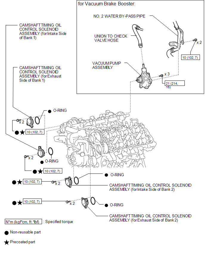
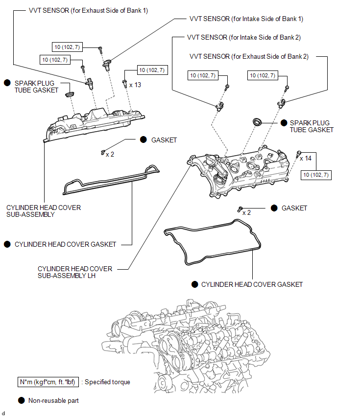
N*m (kgf*cm, ft.*lbf): Specified torque |
â—Ź |
Non-reusable part |
|
*T1 |
Type A: 120 N*m (1224 kgf*cm, 89 ft.*lbf) Type B: 95 N*m (969 kgf*cm, 70 ft.*lbf) |
- |
- |

 Cylinder Block
...
Other materials:
Dtc Check / Clear
DTC CHECK / CLEAR
1. START DIAGNOSTIC MODE
HINT:
Illustrations may differ from the actual vehicle screen depending on
the device settings and options. Therefore, some detailed areas may not
be shown exactly the same as on the actual vehicle screen.
If the system cannot enter d ...
Front Occupant Classification Sensor LH Circuit Malfunction (B1780)
DESCRIPTION
The occupant classification sensor front LH circuit consists of the occupant
detection ECU and the occupant classification sensor front LH.
DTC B1780 is set when a malfunction is detected in the occupant classification
sensor front LH circuit.
DTC No.
DTC Det ...
Inspection
INSPECTION
PROCEDURE
1. INSPECT AUTO HIGH BEAM SWITCH
*a
Component without harness connected
(Auto High Beam Switch)
(a) Check the resistance.
(1) Measure the resistance according to the value(s) in the table below.
Standard Resistance:
Tester C ...
