Toyota Tacoma (2005–2015) Owners Manual: Air conditioning system
Adjusting the settings
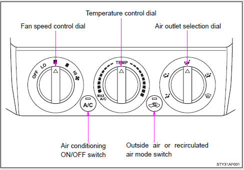
■ Adjusting the temperature setting
Turn the temperature control dial clockwise (warm) or counterclockwise (cool).
If  is not pressed, the system will
blow ambient temperature air or heated air.
is not pressed, the system will
blow ambient temperature air or heated air.
For quick cooling, turn the temperature control dial to the MAX A/C position.
The air conditioning will automatically turn on and the air intake selector will be set to recirculated air mode.
■ Adjusting the fan speed
Turn the fan speed control dial clockwise (increase) or counterclockwise (decrease).
Set the dial to OFF to turn the fan off.
■ Selecting the air outlet
Set the air outlet selection dial to an appropriate position.
The positions between the air outlet selections shown below can also be selected for more detailed adjustment.
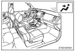
When the dial is set to  , air flows
to the upper body.
, air flows
to the upper body.
 Double Cab models only
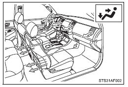
When the dial is set to  , air flows
to the upper body and feet.
, air flows
to the upper body and feet.
 Double Cab models only
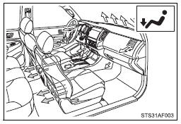
When the dial is set to  , air flows
to the feet.
, air flows
to the feet.
 Double Cab models only
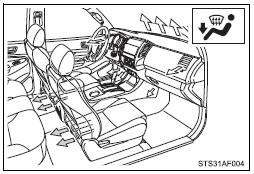
When the dial is set to  , air flows
to the feet and the windshield defogger operates.
, air flows
to the feet and the windshield defogger operates.
The air intake selector is automatically set to outside air mode.
In this position, the air intake selector cannot be changed to the recirculated air mode.
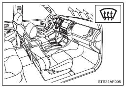
When the dial is set to  , air flows
to the windshield and side windows.
, air flows
to the windshield and side windows.
The air intake selector is automatically set to outside air mode.
In this position, the air intake selector cannot be changed to the recirculated air mode.
■ Switching between outside air and recirculated air modes
Press  .
.
The mode switches between  (outside
air mode) and
(outside
air mode) and  (recirculated air mode)
each time the switch is pressed.
(recirculated air mode)
each time the switch is pressed.

 Adjusting the position of the air outlets
Center outlets
Direct air flow to the left or right, up or down.
Right and left side outlets
Direct air flow to the left or right, up or down.
Opening and closing the air outlets
Center ou ...
Other materials:
Winter driving tips
Carry out the necessary preparations and inspections before driving the vehicle
in winter. Always drive the vehicle in a manner appropriate to the prevailing weather
conditions.
■ Pre-winter preparations
● Use fluids that are appropriate to the prevailing outside temperatures.
• ...
System Description
SYSTEM DESCRIPTION
PRE-COLLISION SYSTEM DESCRIPTION
(a) The pre-collision system uses the pre-collision warning control, pre-collision
brake assist control and pre-collision braking control to help avoid a collision
or reduce the impact if it determines that the possibility of a collision is h ...
Dtc Check / Clear
DTC CHECK / CLEAR
1. CHECK DTC
(a) Connect the Techstream to the DLC3.
(b) Turn the ignition switch to ON.
(c) Turn the Techstream on.
(d) Enter the following menus: Body Electrical / Smart Access or Main Body /
Trouble Codes.
(e) Check the details of the DTC(s) (See page
).
2. CLEAR DTC ...
