DESCRIPTION
This circuit detects whether the ignition switch is ACC or off, and sends this information to the main body ECU (multiplex network body ECU).
WIRING DIAGRAM
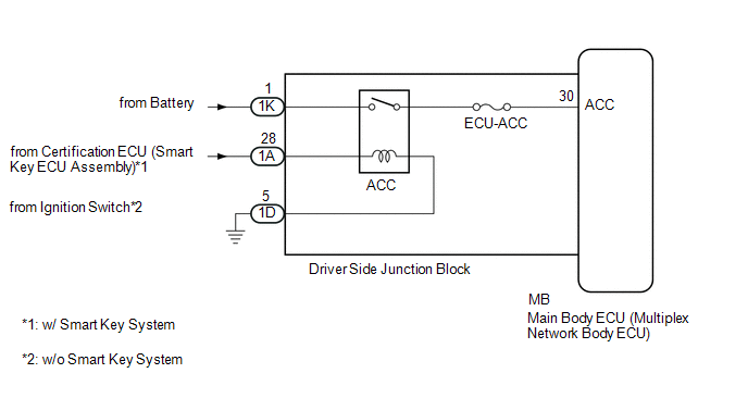
CAUTION / NOTICE / HINT
NOTICE:
- Inspect the fuses for circuits related to this system before performing the following inspection procedure.
- If the main body ECU (multiplex network body ECU) is replaced, refer
to Registration (See page
.gif) ).*1
).*1
- *1: w/ Smart Key System
PROCEDURE
|
1. |
READ VALUE USING TECHSTREAM (ACC SW) |
(a) Connect the Techstream to the DLC3.
(b) Turn the ignition switch to ON.
(c) Turn the Techstream on.
(d) Enter the following menus: Body Electrical / Main Body / Data List.
(e) According to the display on the Techstream, read the Data List.
Main Body|
Tester Display |
Measurement Item/Range |
Normal Condition |
Diagnostic Note |
|---|---|---|---|
|
ACC SW |
Ignition switch ACC signal / ON or OFF |
ON: Ignition switch ACC OFF: Ignition switch off |
"ON" is also displayed for this item when the ignition switch is ON. |
OK:
The display is as specified in the normal condition column.
| OK | .gif) |
PROCEED TO NEXT SUSPECTED AREA SHOWN IN PROBLEM SYMPTOMS TABLE |
|
.gif)
|
2. |
CHECK HARNESS AND CONNECTOR (DRIVER SIDE JUNCTION BLOCK - BATTERY AND BODY GROUND) |
|
(a) Disconnect the driver side junction block connectors. |
|
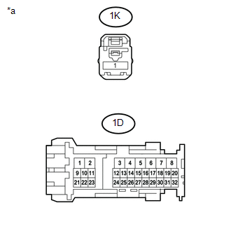
(b) Measure the voltage according to the value(s) in the table below.
Standard Voltage:
|
Tester Connection |
Condition |
Specified Condition |
|---|---|---|
|
1K-1 - Body ground |
Always |
11 to 14 V |
(c) Measure the resistance according to the value(s) in the table below.
Standard Resistance:
|
Tester Connection |
Condition |
Specified Condition |
|---|---|---|
|
1D-5 - Body ground |
Always |
Below 1 Ω |
|
*a |
Front view of wire harness connector (to Driver Side Junction Block) |
| NG | |
REPAIR OR REPLACE HARNESS OR CONNECTOR |
|
|
3. |
CHECK HARNESS AND CONNECTOR (ACC POWER SOURCE CIRCUIT) |
|
(a) Disconnect the driver side junction block connector. |
|
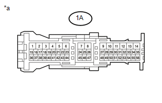
(b) Measure the voltage according to the value(s) in the table below.
Standard Voltage:
|
Tester Connection |
Switch Condition |
Specified Condition |
|---|---|---|
|
1A-28 - Body ground |
Ignition switch ACC |
11 to 14 V |
|
*a |
Front view of wire harness connector (to Driver Side Junction Block) |
| NG | |
REPAIR OR REPLACE HARNESS OR CONNECTOR |
|
|
4. |
CHECK DRIVER SIDE JUNCTION BLOCK |
|
(a) Remove the driver side junction block (See page
|
|
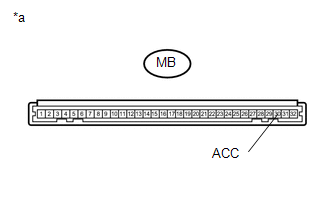
(b) Reconnect the 1K, 1A and 1D driver side junction block connectors.
(c) Measure the voltage according to the value(s) in the table below.
Standard Voltage:
|
Tester Connection |
Switch Condition |
Specified Condition |
|---|---|---|
|
MB-30 (ACC) - Body ground |
Ignition switch ACC |
11 to 14 V |
|
*a |
Component without harness connected (Driver Side Junction Block) |
| OK | |
REPLACE MAIN BODY ECU (MULTIPLEX NETWORK BODY ECU) |
| NG | |
REPLACE DRIVER SIDE JUNCTION BLOCK |