Toyota Tacoma (2015-2018) Service Manual: While Alarm is Armed, Engine Hood is opened but Alarm does not Sound
DESCRIPTION
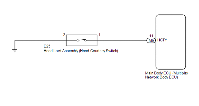
A situation in which the alarm is armed but does not sound when the hood is opened can be caused when the main body ECU (multiplex network body ECU) cannot detect whether the hood courtesy switch is open or closed.
If the alarm does not sound, there may be a malfunction in the hood courtesy switch, main body ECU (multiplex network body ECU) or a wire harness.
WIRING DIAGRAM
CAUTION / NOTICE / HINT
NOTICE:
Before replacing the main body ECU (multiplex network body ECU), refer to Registration
(See page .gif) ).*1
).*1
- *1: w/ Smart Key System
PROCEDURE
|
1. |
CHECK SECURITY INDICATOR LIGHT OPERATION |
(a) Close all doors and the hood.
(b) Lock the doors using the wireless operation*1, key linked operation or entry operation*2.
- *1: w/ Wireless Door Lock System
- *2: w/ Smart Key System
(c) Check that the security indicator light illuminates.
(d) After 30 seconds have elapsed, check that the security indicator light changes from illuminated to flashing.
HINT:
The illumination status of the security indicator light can be used to determine whether the theft deterrent system is set or unset.
| NG | .gif) |
GO TO THEFT DETERRENT SYSTEM CANNOT BE SET OR UNSET |
|
.gif)
|
2. |
READ VALUE USING TECHSTREAM (HOOD COURTESY SW) |
(a) Connect the Techstream to the DLC3.
(b) Turn the ignition switch to ON.
(c) Turn the Techstream on.
(d) Enter the following menus: Body Electrical / Main Body / Data List.
(e) Read the Data List according to the display on the Techstream.
Main Body|
Tester Display |
Measurement Item / Range |
Normal Condition |
Diagnostic Note |
|---|---|---|---|
|
Hood Courtesy SW |
Hood courtesy switch / ON or OFF |
ON: Hood open OFF: Hood closed |
- |
OK:
The Techstream display changes correctly in response to the hood courtesy switch (hood lock assembly) status.
| OK | |
REPLACE MAIN BODY ECU (MULTIPLEX NETWORK BODY ECU) |
|
|
3. |
INSPECT HOOD LOCK ASSEMBLY |
(a) Remove the hood lock assembly (See page
).
(b) Inspect the hood lock assembly (See page
).
| NG | |
REPLACE HOOD LOCK ASSEMBLY |
|
|
4. |
CHECK HARNESS AND CONNECTOR (HOOD LOCK ASSEMBLY - MAIN BODY ECU (MULTIPLEX NETWORK BODY ECU)) |
(a) Disconnect the E25 hood lock assembly connector.
(b) Disconnect the M6 main body ECU (multiplex network body ECU) connector.
(c) Measure the resistance according to the value(s) in the table below.
Standard Resistance:
|
Tester Connection |
Condition |
Specified Condition |
|---|---|---|
|
E25-1 - M6-11 (HCTY) |
Always |
Below 1 Ω |
|
E25-2 - Body ground |
Always |
Below 1 Ω |
|
E25-1 or M6-11 (HCTY) - Body ground |
Always |
10 kΩ or higher |
| OK | |
REPLACE MAIN BODY ECU (MULTIPLEX NETWORK BODY ECU) |
| NG | |
REPAIR OR REPLACE HARNESS OR CONNECTOR |
 While Alarm is Armed, Battery is Reconnected but Alarm does not Sound
DESCRIPTION
While the alarm is armed, the EEPROM inside the main body ECU (multiplex network
body ECU) will remember the armed state even if the battery is disconnected, and
the alarm will sound ...
 Window / Glass
...
Other materials:
Pump Motor Relay (C1253)
DESCRIPTION
The motor relay (semiconductor relay) is built into the master cylinder solenoid
and drives the pump motor based on a signal from the skid control ECU (master cylinder
solenoid).
DTC No.
DTC Detecting Condition
Trouble Areas
C1253
...
On-vehicle Inspection
ON-VEHICLE INSPECTION
PROCEDURE
1. INSPECT AIR CONDITIONER PRESSURE SENSOR (for Automatic Air Conditioning System)
(a) Check the wire harness.
(1) Disconnect the A34 air conditioner pressure sensor connector.
(2) Disconnect the A35 and A36 air conditioning amplifier assembly connector.
...
Reassembly
REASSEMBLY
PROCEDURE
1. INSTALL GENERATOR DRIVE END FRAME BEARING
(a) Using SST and a press, press in a new generator drive end frame bearing.
SST: 09950-60010
09951-00470
SST: 09950-70010
09951-07100
(b) Fit the ta ...
