Toyota Tacoma (2015-2018) Service Manual: Pattern Select Switch Power Mode Circuit
DESCRIPTION
The ECM memory contains the programs for the normal and PWR shift patterns.
By following the programs corresponding to the signals from the pattern select switch assembly, park/neutral position switch and other various sensors, the ECM switches the shift solenoid valves on and off, and controls the transmission gear ratio.
WIRING DIAGRAM

PROCEDURE
|
1. |
INSPECT PATTERN SELECT SWITCH ASSEMBLY |
|
(a) Remove the pattern select switch assembly (See page
|
|
.gif) ).
).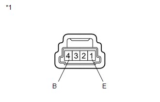
(b) Measure the resistance according to the value(s) in the table below.
Standard Resistance:
|
Tester Connection |
Switch Condition |
Specified Condition |
|---|---|---|
|
1 (E) - 4 (B) |
Pattern select switch assembly pushed |
Below 1 Ω |
|
1 (E) - 4 (B) |
Pattern select switch assembly not pushed |
10 kΩ or higher |
|
*1 |
Pattern Select Switch Assembly |
| NG | .gif) |
REPLACE PATTERN SELECT SWITCH ASSEMBLY |
|
.gif)
|
2. |
CHECK HARNESS AND CONNECTOR (PATTERN SELECT SWITCH ASSEMBLY - BODY GROUND) |
|
(a) Disconnect the pattern select switch assembly connector. |
|
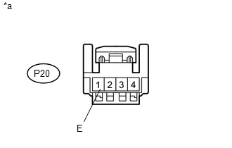
(b) Measure the resistance according to the value(s) in the table below.
Standard Resistance:
|
Tester Connection |
Condition |
Specified Condition |
|---|---|---|
|
P20-1 (E) - Body ground |
Always |
Below 1 Ω |
|
*a |
Front view of wire harness connector (to Pattern Select Switch Assembly)) |
| NG | |
REPAIR OR REPLACE HARNESS OR CONNECTOR |
|
|
3. |
CHECK HARNESS AND CONNECTOR (PATTERN SELECT SWITCH ASSEMBLY - ECM) |
|
(a) Disconnect the ECM connector. |
|
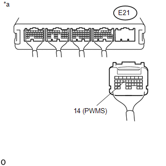
(b) Measure the resistance according to the value(s) in the table below.
Standard Resistance:
|
Tester Connection |
Switch Condition |
Specified Condition |
|---|---|---|
|
E21-14 (PWMS) - Body ground |
Pattern select switch assembly pushed |
Below 1 Ω |
|
E21-14 (PWMS) - Body ground |
Pattern select switch assembly not pushed |
10 kΩ or higher |
|
*a |
Rear view of wire harness connector (to ECM) |
| OK | |
PROCEED TO NEXT SUSPECTED AREA SHOWN IN PROBLEM SYMPTOMS TABLE |
| NG | |
REPAIR OR REPLACE HARNESS OR CONNECTOR |
 Transmission Fluid Temperature Sensor "A" Performance (P0711)
DESCRIPTION
The No. 1 ATF temperature sensor converts the fluid temperature into a resistance
value for use by the ECM.
The ECM applies a voltage to the temperature sensor through terminal THO1 of ...
 Transmission Control Switch Circuit
DESCRIPTION
After moving the shift lever to S, it is possible to switch the shift range between
"1" (S1 range) and "6" (S6 range) using the transmission control switch.
Moving ...
Other materials:
Front Differential Oil Temperature Sensor Circuit Low (P17C7)
DESCRIPTION
This DTC is output when a short to ground in the oil temperature sensor is detected.
DTC No.
Detection Item
DTC Detection Condition
Trouble Area
P17C7
Front Differential Oil Temperature Sensor Circuit Low
...
Steering Angle Sensor (C1A47)
DESCRIPTION
The blind spot monitor sensor receives steering angle signals from the spiral
cable with sensor sub-assembly via CAN communication.
DTC Code
DTC Detection Condition
Trouble Area
C1A47
A fail flag is transmitted from the ste ...
Installation
INSTALLATION
CAUTION / NOTICE / HINT
HINT:
Use the same procedures for both the LH and RH sides.
The procedure described below is for the LH side.
PROCEDURE
1. INSTALL OUTER REAR VIEW MIRROR ASSEMBLY
(a) Engage the claw to install the outer rear view mirror assembly.
(b) Ins ...
