Toyota Tacoma (2015-2018) Service Manual: Terminals Of Ecu
TERMINALS OF ECU
1. TERMINALS OF ECU
 Text in Illustration
|
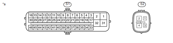
*a |
Component without harness connected (Skid Control ECU (Master Cylinder Solenoid)) |
- |
- |
|
Terminal No. (Symbol) |
Terminal Description |
|---|---|
|
S1-1 (GND1) |
Ground |
|
S1-2 (+BM1) |
Power supply for motor |
|
S1-3 (FR+) |
Front wheel speed sensor RH power supply output |
|
S1-4 (FL-) |
Front wheel speed LH signal input |
|
S1-5 (RR+) |
Rear wheel speed sensor RH power supply output |
|
S1-6 (RL-) |
Rear wheel speed LH signal input |
|
S1-7 (STP) |
Stop light switch input |
|
S1-9 (CSW) |
VSC OFF switch input |
|
S1-11 (CANH) |
CAN communication line H |
|
S1-12 (SP1) |
Speed signal output for speedometer |
|
S1-13 (TRM3) |
A-TRAC switch input*1 CRAWL speed selector switch*2 |
|
S1-16 (STPO) |
Stop light operated relay output |
|
S1-17 (FR-) |
Front wheel speed sensor RH input |
|
S1-18 (FL+) |
Front wheel speed sensor LH power supply output |
|
S1-19 (RR-) |
Rear wheel speed sensor RH input |
|
S1-20 (RL+) |
Rear wheel speed sensor LH power supply output |
|
S1-21 (TRM2) |
CRAWL speed selector switch*2 |
|
S1-25 (CANL) |
CAN communication line L |
|
S1-27 (EXI) |
L4 detection switch input |
|
S1-28 (PKB) |
MTS SET switch input |
|
S1-29 (EXI4) |
4WD detection switch input |
|
S1-31 (+BS) |
Power supply for solenoid |
|
S1-32 (GND2) |
Ground |
|
S1-41 (LBL) |
Brake fluid level warning switch input |
|
S1-43 (TRS) |
CRAWL ON/OFF switch*2 |
|
S1-44 (TRM1) |
CRAWL speed selector switch*2 |
|
S1-45 (STP2) |
Stop light switch input |
|
S1-46 (IG1) |
IG1 power supply |
|
S2-1 (IG2) |
IG2 power supply |
|
S2-2 (+BM2) |
Power supply for motor |
|
S2-4 (GND3) |
Ground |
- *1: for Manual Transmission
- *2: for Automatic Transmission
2. TERMINAL INSPECTION
Disconnect the connector and measure the voltage or resistance on the wire harness side.
HINT:
Voltage cannot be measured with the connector connected to the skid control ECU (master cylinder solenoid) as the connector is water resistant.
 Text in Illustration
|
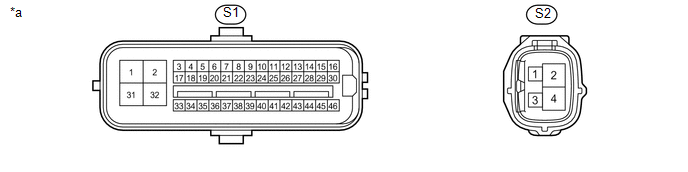
*a |
Front view of wire harness connector (Skid Control ECU (Master Cylinder Solenoid)) |
- |
- |
|
Terminal No. (Symbol) |
Wiring Color |
Terminal Description |
Condition |
Specified Condition |
|---|---|---|---|---|
|
S1-1 (GND1) - Body ground |
W-B - Body ground |
Ground |
Always |
Below 1 Ω |
|
S1-2 (+BM1) - Body ground |
B - Body ground |
Power supply for motor from battery |
Always |
11 to 14 V |
|
S1-7 (STP) - Body ground |
SB - Body ground |
Stop light switch input |
Stop light switch off (Brake pedal released) |
Below 1.5 V |
|
Stop light switch on (Brake pedal depressed) |
8 to 14 V |
|||
|
S1-9 (CSW) - Body ground |
GR - Body ground |
VSC OFF switch input |
VSC OFF switch off |
10 kΩ or higher |
|
VSC OFF switch on and hold |
Below 1 Ω |
|||
|
S1-16 (STPO) - Body ground |
B - Body ground |
Stop light operated relay output |
Ignition switch off |
Below 1 V |
|
Ignition switch ON |
11 to 14 V |
|||
|
S1-31 (+BS) - Body ground |
R - Body ground |
Power supply for solenoid from battery |
Always |
11 to 14 V |
|
S1-32 (GND2) - Body ground |
W-B - Body ground |
Ground |
Always |
Below 1 Ω |
|
S1-41 (LBL) - Body ground |
V - Body ground |
Brake fluid level warning switch input |
Brake fluid level min. -5 mm |
Below 1 Ω |
|
Brake fluid level max. |
1.9 to 2.1 kΩ |
|||
|
S1-45 (STP2) - Body ground |
L - Body ground |
Stop light switch input |
Stop light switch off (Brake pedal released) |
Below 1.5 V |
|
Stop light switch on (Brake pedal depressed) |
8 to 14 V |
|||
|
S1-46 (IG1) - Body ground |
G - Body ground |
IG1 power supply |
Ignition switch off |
Below 1 V |
|
Ignition switch ON |
11 to 14 V |
|||
|
S2-1 (IG2) - Body ground |
BE - Body ground |
IG2 power supply |
Ignition switch off |
Below 1 V |
|
Ignition switch ON |
11 to 14 V |
|||
|
S2-2 (+BM2) - Body ground |
B - Body ground |
Power supply for motor from battery |
Always |
11 to 14 V |
|
S2-4 (GND3) - Body ground |
W-B - Body ground |
Ground |
Always |
Below 1 Ω |
 Test Mode Procedure
TEST MODE PROCEDURE
1. TEST MODE PROCEDURE (for Using Techstream)
HINT:
If the ignition switch is turned from the ON to the ACC or LOCK position
during test mode, DTCs related to the si ...
 Diagnosis System
DIAGNOSIS SYSTEM
1. DIAGNOSIS
(a) If the skid control ECU (master cylinder solenoid) detects a malfunction,
the ABS and/or BRAKE warning lights and the slip indicator lights come on in accordance ...
Other materials:
Replacement
REPLACEMENT
CAUTION / NOTICE / HINT
CAUTION:
Prolonged and repeated contact with engine oil will result in the removal
of natural oils from the skin, leading to dryness, irritation and dermatitis.
In addition, used engine oil contains potentially harmful contaminants which
may ...
Transmission Fluid Temperature Sensor "B" Circuit Short to Ground (P274011)
DESCRIPTION
The No. 2 ATF temperature sensor is installed in the transmission valve body
assembly.
If the ECM detects an abnormally high ATF temperature near this sensor, it illuminates
the warning indicator.
HINT:
The temperature of ATF easily rises when towing, climbing hills, in
...
Rear Leaf Spring
Components
COMPONENTS
ILLUSTRATION
Disassembly
DISASSEMBLY
PROCEDURE
1. REMOVE BUSH
(a) Fix the spring in a vise.
(b) Using a hack saw, cut both ends off the bushes.
(c) Using SST and a press, press out the 2 bushes.
SST: 09950-60010
09951-00350
SST: 09950-70010
...
