Toyota Tacoma (2015-2018) Service Manual: Terminals Of Ecu
TERMINALS OF ECU
1. CHECK POWER WINDOW REGULATOR MASTER SWITCH ASSEMBLY
(a) for Double Cab
(1) Disconnect the P18 power window regulator master switch assembly connector.

(2) Measure the voltage and resistance according to the value(s) in the table below.
HINT:
Measure the values on the wire harness side with the connector disconnected.
|
Terminal No. (Symbol) |
Wiring Color |
Terminal Description |
Condition |
Specified Condition |
|---|---|---|---|---|
|
P18-3 (B) - P18-1 (GND) |
R - W-B |
Power supply |
Always |
11 to 14 V |
|
P18-1 (GND) - Body ground |
W-B - Body ground |
Ground |
Always |
Below 1 Ω |
If the result is not as specified, there may be a malfunction in the wire harness.
(3) Reconnect the P18 power window regulator master switch assembly connector.
(4) Measure the voltage according to the value(s) in the table below.
|
Terminal No. (Symbol) |
Wiring Color |
Terminal Description |
Condition |
Specified Condition |
|---|---|---|---|---|
|
P18-5 (DOWN) - P18-1 (GND) |
SB - W-B |
Power window motor DOWN output |
Ignition switch ON, power window regulator master switch assembly off |
11 to 14 V |
|
Ignition switch ON, power window regulator master switch assembly DOWN (Manual operation) |
Below 1 V |
|||
|
P18-4 (UP) - P18-1 (GND) |
L - W-B |
Power window motor UP output |
Ignition switch ON, power window regulator master switch assembly off |
11 to 14 V |
|
Ignition switch ON, power window regulator master switch assembly UP (Manual operation) |
Below 1 V |
|||
|
P18-13 (PWS) - P18-1 (GND) |
W - W-B |
P/W MAIN relay operation signal |
Ignition switch ON |
11 to 14 V |
(b) for Access Cab
(1) Disconnect the P23 power window regulator master switch assembly connector.

(2) Measure the voltage and resistance according to the value(s) in the table below.
HINT:
Measure the values on the wire harness side with the connector disconnected.
|
Terminal No. (Symbol) |
Wiring Color |
Terminal Description |
Condition |
Specified Condition |
|---|---|---|---|---|
|
P23-11 (B) - P23-12 (GND) |
R - W-B |
Power supply |
Always |
11 to 14 V |
|
P23-12 (GND) - Body ground |
W-B - Body ground |
Ground |
Always |
Below 1 Ω |
If the result is not as specified, there may be a malfunction in the wire harness.
(3) Reconnect the P18 power window regulator master switch assembly connector.
(4) Measure the voltage according to the value(s) in the table below.
|
Terminal No. (Symbol) |
Wiring Color |
Terminal Description |
Condition |
Specified Condition |
|---|---|---|---|---|
|
P23-15 (DOWN) - P23-12 (GND) |
SB - W-B |
Power window motor DOWN output |
Ignition switch ON, power window regulator master switch assembly off |
11 to 14 V |
|
Ignition switch ON, power window regulator master switch assembly DOWN (Manual operation) |
Below 1 V |
|||
|
P23-20 (UP) - P23-12 (GND) |
L - W-B |
Power window motor UP output |
Ignition switch ON, power window regulator master switch assembly off |
11 to 14 V |
|
Ignition switch ON, power window regulator master switch assembly UP (Manual operation) |
Below 1 V |
2. CHECK FRONT POWER WINDOW REGULATOR SWITCH ASSEMBLY RH
(a) Disconnect the P21 front power window regulator switch assembly RH connector.

(b) Measure the resistance according to the value(s) in the table below.
HINT:
Measure the values on the wire harness side with the connector disconnected.
|
Terminal No. (Symbol) |
Wiring Color |
Terminal Description |
Condition |
Specified Condition |
|---|---|---|---|---|
|
P21-7 (GND) - Body ground |
W-B - Body ground |
Ground |
Always |
Below 1 Ω |
If the result is not as specified, there may be a malfunction in the wire harness.
(c) Reconnect the P21 front power window regulator switch assembly RH connector.
(d) Measure the voltage according to the value(s) in the table below.
|
Terminal No. (Symbol) |
Wiring Color |
Terminal Description |
Condition |
Specified Condition |
|---|---|---|---|---|
|
P21-2 (IG) - P21-7 (GND) |
P - W-B |
IG power supply |
Ignition switch ON |
11 to 14 V |
|
Ignition switch off |
Below 1 V |
|||
|
P21-5 (UP) - P21-7 (GND) |
L - W-B |
Power window motor up output |
Ignition switch ON, front power window regulator switch assembly RH not pushed or pulled |
11 to 14 V |
|
Ignition switch ON, front passenger door power window moving, front power window regulator switch assembly RH pulled halfway up (Manual operation) |
Below 1 V |
|||
|
Ignition switch ON, front passenger door power window fully open |
11 to 14 V |
|||
|
Ignition switch ON, front passenger door power window moving, front power window regulator switch assembly RH fully pulled up (Auto operation) |
Below 1 V |
|||
|
Ignition switch ON, front passenger door power window fully closed |
11 to 14 V |
|||
|
P21-4 (DOWN) - P21-7 (GND) |
Y - W-B |
Power window motor down output |
Ignition switch ON, front power window regulator switch assembly RH not pushed or pulled |
11 to 14 V |
|
Ignition switch ON, front passenger door power window moving, front power window regulator switch assembly RH pushed halfway down (Manual operation) |
Below 1 V |
|||
|
Ignition switch ON, front passenger door power window fully closed |
11 to 14 V |
|||
|
Ignition switch ON, front passenger door power window moving, front power window regulator switch assembly RH fully pushed down (Auto operation) |
Below 1 V |
|||
|
Ignition switch ON, front passenger door power window fully open |
11 to 14 V |
|||
|
P21-8 (AUTO) - P21-7 (GND) |
R - W-B |
Power window motor up output |
Ignition switch ON, front passenger door power window fully open |
11 to 14 V |
|
Ignition switch ON, front passenger door power window moving, front power window regulator switch assembly RH fully pulled up (Auto operation) |
Below 1 V |
|||
|
Ignition switch ON, front passenger door power window fully closed |
11 to 14 V |
|||
|
Power window motor down output |
Ignition switch ON, front passenger door power window fully closed |
11 to 14 V |
||
|
Ignition switch ON, front passenger door power window moving, front power window regulator switch assembly RH fully pushed down (Auto operation) |
Below 1 V |
|||
|
Ignition switch ON, front passenger door power window fully open |
11 to 14 V |
If the result is not as specified, the front power window regulator switch assembly RH may have a malfunction.
3. CHECK FRONT POWER WINDOW REGULATOR MOTOR ASSEMBLY LH
(a) Disconnect the P24 front power window regulator motor assembly LH connector.
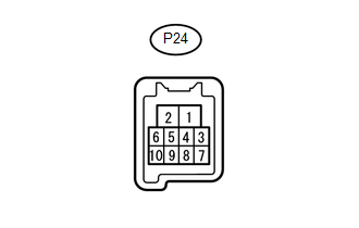
(b) Measure the voltage and resistance according to the value(s) in the table below.
HINT:
Measure the values on the wire harness side with the connector disconnected.
|
Terminal No. (Symbol) |
Wiring Color |
Terminal Description |
Condition |
Specified Condition |
|---|---|---|---|---|
|
P24-1 (GND) - Body ground |
W-B - Body ground |
Ground |
Always |
Below 1 Ω |
|
P24-2 (B) - Body ground |
R - Body ground |
Power supply |
Ignition switch ON |
11 to 14 V |
If the result is not as specified, there may be a malfunction in the wire harness.
(c) Reconnect the P24 front power window regulator motor assembly LH connector.
(d) Measure the voltage according to the value(s) in the table below.
|
Terminal No. (Symbol) |
Wiring Color |
Terminal Description |
Condition |
Specified Condition |
|---|---|---|---|---|
|
P24-7 (DOWN) - P24-1 (GND) |
SB - W-B |
Power window motor DOWN input |
Ignition switch ON, power window regulator master switch assembly off |
11 to 14 V |
|
Ignition switch ON, power window regulator master switch assembly DOWN (Manual operation) |
Below 1 V |
|||
|
Ignition switch ON, driver side power window fully closed |
11 to 14 V |
|||
|
Ignition switch ON, driver side power window fully DOWN (AUTO DOWN position) |
Below 1 V |
|||
|
Ignition switch ON, driver side power window fully stopped (DOWN) |
11 to 14 V |
|||
|
P24-10 (UP) - P24-1 (GND) |
L - W-B |
Power window motor UP input |
Ignition switch ON, power window regulator master switch assembly off |
11 to 14 V |
|
Ignition switch ON, power window regulator master switch assembly UP (Manual operation) |
Below 1 V |
|||
|
Ignition switch ON, driver side power window fully open |
11 to 14 V |
|||
|
Ignition switch ON, driver side power window fully UP (AUTO UP position) |
Below 1 V |
|||
|
Ignition switch ON, driver side power window fully stopped (UP) |
11 to 14 V |
If the result is not as specified, the front power window regulator motor assembly LH may have a malfunction.
4. CHECK FRONT POWER WINDOW REGULATOR MOTOR ASSEMBLY RH
(a) Disconnect the P22 front power window regulator motor assembly RH connector.
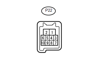
(b) Measure the voltage and resistance according to the value(s) in the table below.
HINT:
Measure the values on the wire harness side with the connector disconnected.
|
Terminal No. (Symbol) |
Wiring Color |
Terminal Description |
Condition |
Specified Condition |
|---|---|---|---|---|
|
P22-1 (GND) - Body ground |
W-B - Body ground |
Ground |
Always |
Below 1 Ω |
|
P22-2 (B) - Body ground |
W - Body ground |
Power supply |
Ignition switch ON |
11 to 14 V |
If the result is not as specified, there may be a malfunction in the wire harness.
(c) Reconnect the P22 front power window regulator motor assembly RH connector.
(d) Measure the voltage according to the value(s) in the table below.
|
Terminal No. (Symbol) |
Wiring Color |
Terminal Description |
Condition |
Specified Condition |
|---|---|---|---|---|
|
P22-4 (AUTO) - P22-1 (GND) |
R - W-B |
Power window motor AUTO UP input |
Ignition switch ON, front passenger side power window fully open |
11 to 14 V |
|
Ignition switch ON, front passenger side power window fully UP (AUTO UP position) |
Below 1 V |
|||
|
Ignition switch ON, front passenger side power window fully stopped (UP) |
11 to 14 V |
|||
|
Power window motor AUTO DOWN input |
Ignition switch ON, front passenger side power window fully closed |
11 to 14 V |
||
|
Ignition switch ON, front passenger side power window fully DOWN (AUTO DOWN position) |
Below 1 V |
|||
|
Ignition switch ON, front passenger side power window fully stopped (DOWN) |
11 to 14 V |
|||
|
P22-7 (DOWN) - P22-1 (GND) |
Y - W-B |
Power window motor DOWN input |
Ignition switch ON, front power window regulator switch assembly RH off |
11 to 14 V |
|
Ignition switch ON, front power window regulator switch assembly RH DOWN (Manual operation) |
Below 1 V |
|||
|
Ignition switch ON, front passenger side power window fully closed |
11 to 14 V |
|||
|
Ignition switch ON, front passenger side power window fully DOWN (AUTO DOWN position) |
Below 1 V |
|||
|
Ignition switch ON, front passenger side power window fully stopped (DOWN) |
11 to 14 V |
|||
|
P22-10 (UP) - P22-1 (GND) |
L - W-B |
Power window motor UP input |
Ignition switch ON, front power window regulator switch assembly RH off |
11 to 14 V |
|
Ignition switch ON, front power window regulator switch assembly RH UP (Manual operation) |
Below 1 V |
|||
|
Ignition switch ON, front passenger side power window fully open |
11 to 14 V |
|||
|
Ignition switch ON, front passenger side power window fully UP (AUTO UP position) |
Below 1 V |
|||
|
Ignition switch ON, front passenger side power window fully stopped (UP) |
11 to 14 V |
If the result is not as specified, the front power window regulator motor assembly RH may have a malfunction.
5. CHECK MAIN BODY ECU AND DRIVER SIDE JUNCTION BLOCK
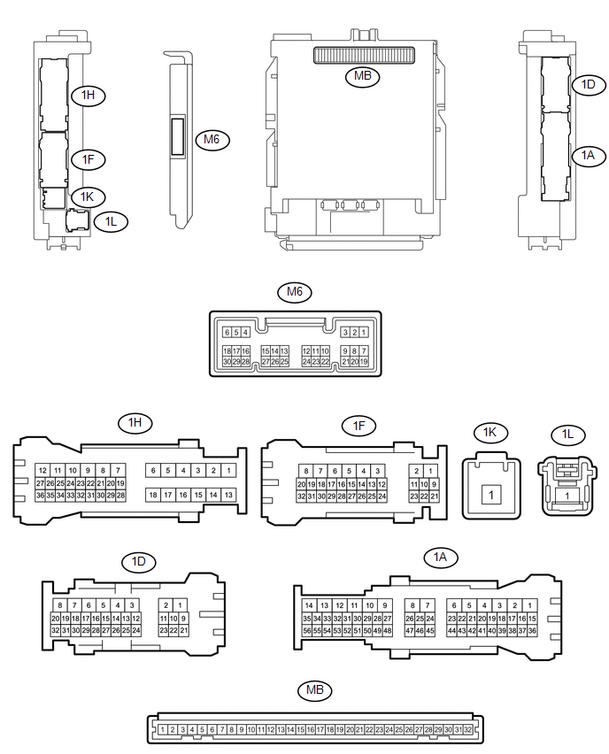
(a) Remove the main body ECU.
(b) Disconnect the M6 main body ECU connector.
(c) Measure the voltage and resistance according to the value(s) in the table below.
HINT:
Measure the values on the wire harness side with the connector disconnected.
|
Terminal No. (Symbol) |
Wiring Color |
Terminal Description |
Condition |
Specified Condition |
|---|---|---|---|---|
|
M6-6 (FLCY) - Body ground |
Y |
Front door courtesy light switch LH input |
Driver side door Closed (off) |
10 kΩ or higher |
|
Driver side door Open (on) |
Below 1 Ω |
|||
|
M6-27 (FRCY) - Body ground |
LG |
Front door courtesy light switch RH input |
Front passenger side door Closed (off |
10 kΩ or higher |
|
Front passenger side door Open (on) |
Below 1 Ω |
|||
|
MB-11 (GND1) - Body ground |
- |
Ground |
Always |
Below 1 Ω |
|
MB-30 (ACC) - Body ground |
- |
Ignition power supply (ACC signal) |
Ignition switch ACC |
11 to 14 V |
|
Ignition switch off |
Below 1 V |
|||
|
MB-31 (BECU) - Body ground |
- |
Battery power supply |
Always |
11 to 14 V |
|
MB-32 (IG) - Body ground |
- |
Battery power supply |
Always |
11 to 14 V |
|
1D-5 (GND1) - Body ground |
W-B - Body ground |
Ground |
Always |
Below 1 Ω |
If the result is not as specified, there may be a malfunction on the wire harness side.
(d) Reinstall the main body ECU.
(e) Reconnect the M6 main body ECU connector.
(f) Measure the voltage according to the value(s) in the table below.
|
Terminal No. (Symbol) |
Wiring Color |
Terminal Description |
Condition |
Specified Condition |
|---|---|---|---|---|
|
M6-6 (FLCY) - Body ground |
Y - Body ground |
Front door courtesy light switch LH input |
Driver side door open |
Below 1 V |
|
Front door courtesy light switch LH input |
Driver side door closed |
11 to 14 V |
||
|
M6-27 (FRCY) - Body ground |
LG - Body ground |
Front door courtesy light switch RH input |
Front passenger side door open |
Below 1 V |
|
Front door courtesy light switch RH input |
Front passenger side door closed |
11 to 14 V |
If the result is not as specified, the ECU may have a malfunction.
 Dtc Check / Clear
DTC CHECK / CLEAR
1. CHECK DTC
(a) Connect the Techstream to the DLC3.
(b) Turn the ignition switch to ON.
(c) Turn the Techstream on.
(d) Enter the following menus: Body Electrical / (desired sy ...
 Data List / Active Test
DATA LIST / ACTIVE TEST
1. READ DATA LIST
HINT:
Using the Techstream to read the Data List allows the values or states of switches,
sensors, actuators and other items to be read without removing ...
Other materials:
Removal
REMOVAL
CAUTION / NOTICE / HINT
HINT:
If the bumper is damaged, there is a possibility that the installation area of
the blind spot monitor sensor may be deformed and the blind spot monitor system
may not operate correctly, so visually inspect the blind spot monitor sensor installation
area ...
A-TRAC Indicator Light does not Come ON
DESCRIPTION
The A-TRAC does not operate even if the A-TRAC switch is pressed under the following
conditions:
The TRAC or VSC system is faulty.
The temperature inside the hydraulic brake booster increases and the
A-TRAC operation is suspended.
WIRING DIAGRAM
Refer to A-TRAC ...
Installation
INSTALLATION
PROCEDURE
1. INSTALL ENGINE COOLANT TEMPERATURE SENSOR
2. INSTALL ENGINE OIL PRESSURE SWITCH ASSEMBLY
3. INSTALL IGNITION COIL ASSEMBLY
4. INSTALL FUEL INJECTOR SEAL
5. INSTALL FUEL INJECTOR ASSEMBLY
6. INSTALL FUEL DELIVERY PIPE RH
7. INSTALL FUEL DELIVERY PIP ...
