Toyota Tacoma (2015-2018) Service Manual: Terminals Of Ecm
TERMINALS OF ECM
1. CHECK ECM
HINT:
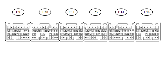
The standard normal voltage between each pair of ECM terminals is shown in the table below. The appropriate conditions for checking each pair of terminals are also indicated. The result of checks should be compared with the standard normal voltage for that pair of terminals, displayed in the Specified Condition column. The illustration above can be used as a reference to identify the ECM terminal locations.
|
Terminal No. (Symbol) |
Wiring Color |
Terminal Description |
Condition |
Specified Condition |
|---|---|---|---|---|
|
E14-2 (BATT) - E11-1 (E1) |
L - W-B |
Battery (for measuring battery voltage and for ECM memory) |
Always |
11 to 14 V |
|
E11-1 (E1) - Body ground |
W-B - Body ground |
Ground circuit of ECM |
Always |
Below 1 Ω |
|
E9-34 (LIN) - Body ground |
L - Body ground |
LIN communication line |
Ignition switch off |
10 kΩ or higher |
 Diagnosis System
DIAGNOSIS SYSTEM
1. DLC3 (Data Link Connector 3)
(a) Check the DLC3 (See page ).
2. BATTERY VOLTAGE
Standard voltage:
11 to 14 V
If the voltage is below 11 V, replace or recharge the battery. ...
 Dtc Check / Clear
DTC CHECK / CLEAR
1. CHECK DTC
(a) Connect the Techstream to the DLC3.
(b) Turn the ignition switch to ON.
(c) Turn the Techstream on.
(d) Enter the following menus: Powertrain / Engine / Trouble ...
Other materials:
Vacuum Warning Switch
Components
COMPONENTS
ILLUSTRATION
On-vehicle Inspection
ON-VEHICLE INSPECTION
PROCEDURE
1. INSPECT BRAKE FLUID LEVEL IN RESERVOIR
2. INSPECT BRAKE BOOSTER ASSEMBLY
3. INSPECT VACUUM WARNING SWITCH ASSEMBLY
(a) Start the engine and stop it after 1 or 2 minutes.
(b) Disconnect the ...
Heater Relay
Inspection
INSPECTION
PROCEDURE
1. INSPECT HEATER RELAY
(a) Check the resistance.
(1) Using an ohmmeter, measure the resistance between each terminal.
Standard:
Tester Connection
Specified Condition
3 - 4
...
Headlight Relay
Inspection
INSPECTION
PROCEDURE
1. INSPECT HEADLIGHT RELAY
(a) Check the resistance.
(1) Using an ohmmeter, measure the resistance between the terminals.
Standard:
Tester Connection
Specified Condition
3-5
10 kΩ or higher
...
