Toyota Tacoma (2015-2018) Service Manual: Steering Pad Switch Circuit
DESCRIPTION
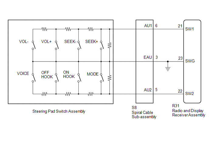
This circuit sends an operation signal from the steering pad switch assembly to the radio and display receiver assembly.
If there is an open in the circuit, the audio system cannot be operated using the steering pad switch assembly.
If there is a short in the circuit, the same condition as when a switch is continuously depressed occurs.
Therefore, the radio and display receiver assembly cannot be operated using the steering pad switch assembly, and also the radio and display receiver assembly itself cannot function.
WIRING DIAGRAM
CAUTION / NOTICE / HINT
NOTICE:
The vehicle is equipped with a Supplemental Restraint System (SRS) which includes
components such as airbags. Before servicing (including removal or installation
of parts), be sure to read the precautionary notice for the Supplemental Restraint
System (See page .gif) ).
).
PROCEDURE
|
1. |
CHECK HARNESS AND CONNECTOR (STEERING PAD SWITCH SIGNAL) |
|
(a) Disconnect the radio and display receiver assembly connector. |
|
(b) Measure the resistance according to the value(s) in the table below.
Standard Resistance:
|
Tester Connection |
Switch Condition |
Specified Condition |
|---|---|---|
|
R31-21 (SW1) - R31-23 (SWG) |
No switch is pushed |
99 to 101 kΩ |
|
Volume+ is pushed |
1000 to 1020 Ω |
|
|
Volume- is pushed |
3178 to 3242 Ω |
|
|
Seek+ is pushed |
Below 2.5 Ω |
|
|
Seek- is pushed |
327 to 333 Ω |
|
|
R31-22 (SW2) - R31-23 (SWG) |
No switch is pushed |
99 to 101 kΩ |
|
MODE switch is pushed |
Below 2.5 Ω |
|
|
On Hook switch is pushed |
327 to 333 Ω |
|
|
Off Hook switch is pushed |
1000 to 1020 Ω |
|
|
Voice switch is pushed |
3178 to 3242 Ω |
|
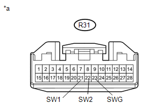
*a |
Front view of wire harness connector (to Radio and Display Receiver Assembly) |
| OK | .gif) |
PROCEED TO NEXT SUSPECTED AREA SHOWN IN PROBLEM SYMPTOMS TABLE |
|
.gif)
|
2. |
INSPECT STEERING PAD SWITCH ASSEMBLY |
(a) Remove the steering pad switch assembly (See page
).
(b) Inspect the steering pad switch assembly (See page
).
| NG | |
REPLACE STEERING PAD SWITCH ASSEMBLY |
|
|
3. |
INSPECT SPIRAL CABLE WITH SENSOR SUB-ASSEMBLY |
(a) Remove the spiral cable with sensor sub-assembly (See page
).
(b) Inspect the spiral cable with sensor sub-assembly (See page
).
| OK | |
REPAIR OR REPLACE HARNESS OR CONNECTOR (RADIO AND DISPLAY RECEIVER ASSEMBLY - SPIRAL CABLE WITH SENSOR SUB-ASSEMBLY) |
| NG | |
REPLACE SPIRAL CABLE WITH SENSOR SUB-ASSEMBLY |
 Vehicle Speed Signal Circuit between Radio Receiver and Combination Meter
DESCRIPTION
for Audio Function:
The radio and display receiver assembly receives a vehicle speed signal
from the combination meter assembly and sends the signal to radio and display
...
 Illumination Circuit
DESCRIPTION
Power is supplied to the radio and display receiver assembly and steering pad
switch assembly illumination when the light control switch is in the TAIL or HEAD
position.
WIRING DIAGR ...
Other materials:
On-vehicle Inspection
ON-VEHICLE INSPECTION
PROCEDURE
1. INSPECT SPEEDOMETER
(a) Check speedometer operation.
NOTICE:
The meter ECU receives the vehicle speed signal from the skid control
ECU via CAN communication. Therefore, perform the following inspection referring
to values on the Data List of th ...
If you think something is wrong
If you notice any of the following symptoms, your vehicle probably needs adjustment
or repair. Contact your Toyota dealer as soon as possible.
■ Visible sympt
● Fluid leaks under the vehicle (Water dripping from the air conditioning after
use is normal.)
● Flat-looking tires ...
Removal
REMOVAL
PROCEDURE
1. PRECAUTION
CAUTION:
Be sure to read Precaution thoroughly before servicing (See page
).
NOTICE:
After turning the ignition switch off, waiting time may be required before disconnecting
the cable from the negative (-) battery terminal. Therefore, make sure to read the
...
