Toyota Tacoma (2015-2018) Service Manual: Pattern Select Switch
Components
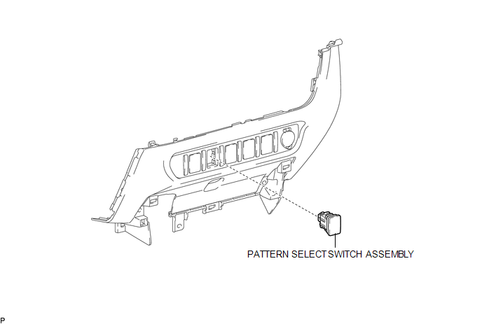
COMPONENTS
ILLUSTRATION
Removal
REMOVAL
PROCEDURE
1. REMOVE INSTRUMENT PANEL LOWER CENTER FINISH PANEL
(See page .gif) )
)
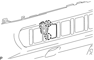
2. REMOVE PATTERN SELECT SWITCH ASSEMBLY
|
(a) Detach the 2 claws to remove the pattern select switch assembly from the instrument panel lower center finish panel. |
|
Inspection
INSPECTION
PROCEDURE
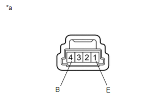
1. INSPECT PATTERN SELECT SWITCH ASSEMBLY
|
(a) Measure the resistance according to the value(s) in the table below. Text in Illustration
Standard Resistance:
If the result is not as specified, replace the pattern select switch assembly. |
|
Installation
INSTALLATION
PROCEDURE
1. INSTALL PATTERN SELECT SWITCH ASSEMBLY
(a) Attach the 2 claws to install the pattern select switch assembly to the instrument panel lower center finish panel.
2. INSTALL INSTRUMENT PANEL LOWER CENTER FINISH PANEL
(See page .gif) )
)
 Installation
INSTALLATION
PROCEDURE
1. INSTALL PARK/NEUTRAL POSITION SWITCH
HINT:
Make sure that the manual valve lever shaft has not been rotated prior to installing
the park/neutral position switch as the ...
 Automatic Transmission Unit(for 2gr-fks)
Components
COMPONENTS
ILLUSTRATION
ILLUSTRATION
ILLUSTRATION
ILLUSTRATION
ILLUSTRATION
ILLUSTRATION
ILLUSTRATION
ILLUSTRATION
ILLUSTRATION
...
Other materials:
Removal
REMOVAL
PROCEDURE
1. REMOVE FRONT FENDER MUDGUARD (w/ Mudguard)
Click here
2. REMOVE FRONT FENDER WHEEL OPENING MOULDING (w/ Over Fender)
Click here
3. REMOVE FRONT NO. 1 WHEEL OPENING EXTENSION PAD (w/ Front Spoiler)
(a) Remove 9 screws and front No. 1 wheel opening extension ...
Data List / Active Test
DATA LIST / ACTIVE TEST
1. DATA LIST
HINT:
Using the Techstream to read the Data List allows the values or states of switches,
sensors, actuators and other items to be read without removing any parts. This non-intrusive
inspection can be very useful because intermittent conditions or signals ...
Installation
INSTALLATION
CAUTION / NOTICE / HINT
PROCEDURE
1. INSTALL REAR AIRBAG SENSOR LH
(a) Check that the ignition switch is OFF.
(b) Check that the cable is disconnected from the battery negative (-) terminal.
CAUTION:
After disconnecting the cable from the terminal, wait for at least 90 seconds
...
