Toyota Tacoma (2015-2018) Service Manual: System Diagram
SYSTEM DIAGRAM
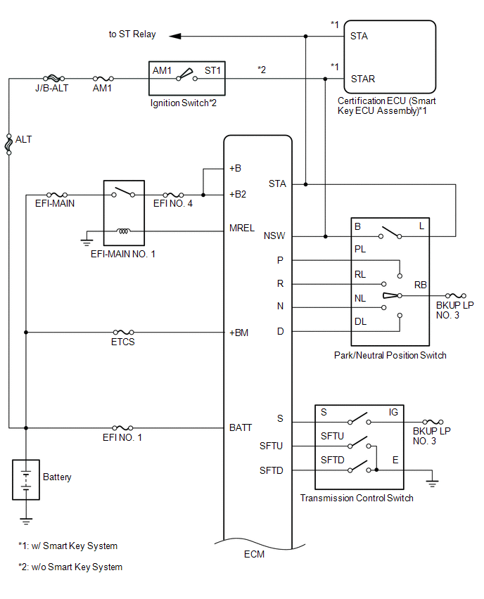
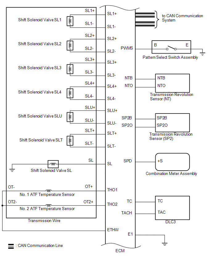
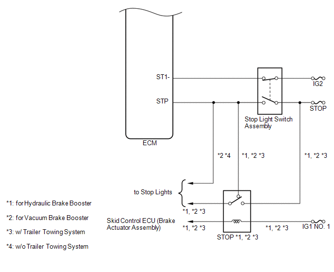
The configuration of the electronic control system in the AC60E automatic transmission is as shown in the following chart.
 System Description
SYSTEM DESCRIPTION
1. SYSTEM DESCRIPTION
(a) The Electronic Controlled Automatic Transmission (ECT) is an automatic transmission
that has its shift timing electronically controlled by the ECM. The ...
 Hydraulic Test
HYDRAULIC TEST
1. PERFORM HYDRAULIC TEST
(a) Measure the line pressure.
CAUTION:
The line pressure test should always be performed with at least 2 people. One
person should observe the condition ...
Other materials:
Removal
REMOVAL
PROCEDURE
1. REMOVE SPIRAL CABLE WITH SENSOR SUB-ASSEMBLY
(See page )
2. REMOVE WINDSHIELD WIPER SWITCH ASSEMBLY
3. REMOVE HEADLIGHT DIMMER SWITCH ASSEMBLY
(a) Disconnect the connector.
(b) Disengage the 3 claws to remove the he ...
Transmission Fluid Temperature Sensor "A" Circuit Range/Performance (P071000)
DESCRIPTION
The No. 1 ATF temperature sensor converts the fluid temperature into a resistance
value for use by the ECM.
The ECM applies a voltage to the temperature sensor through terminal THO1 of
the ECM.
The sensor resistance changes with the ATF temperature. As the temperature becomes
hi ...
Freeze Frame Data
FREEZE FRAME DATA
1. FREEZE FRAME DATA
(a) Using the Techstream, check the vehicle condition (ECU, sensor) when the
brake system operates or a DTC is output.
2. CHECK FREEZE FRAME DATA WHEN BRAKE SYSTEM OPERATES
(a) Freeze frame data is stored when the brake system operates. The freeze frame
...
