Toyota Tacoma (2015-2018) Service Manual: Hydraulic Test
HYDRAULIC TEST
1. PERFORM HYDRAULIC TEST
(a) Measure the line pressure.
CAUTION:
The line pressure test should always be performed with at least 2 people. One person should observe the condition of the wheels and wheel chocks while the other is performing the test.
NOTICE:
- Perform the test while the ATF (Automatic Transmission Fluid) temperature is between 50 and 80°C (122 and 176°F).
- Be careful to prevent the hose of SST from interfering with the exhaust pipe.
- This check must be conducted after checking and adjusting the engine.
- Perform the test with the air conditioning off.
- When conducting stall test, do not continue for more than 5 seconds.
- When performing the stall speed test more than once, make sure to wait 15 seconds or more between tests.
(1) Warm up the ATF (Automatic Transmission Fluid).
(2) Turn the ignition switch off.
(3) Lift the vehicle up.
(4) Remove the test plug from the transmission case and connect SST.
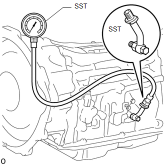
SST: 09993-19015
09993-00010
09993-00040
(5) Lower the vehicle.
(6) Fully apply the parking brake and chock the 4 wheels.
(7) Start the engine and check the idling speed.
(8) Keep your left foot pressed firmly on the brake pedal and move the shift lever to D.
(9) Fully depress the accelerator pedal with your right foot. Quickly read the highest line pressure when the engine speed reaches the stall speed.
(10) In the same manner, perform the test with the shift lever in R.
Specified Line Pressure|
Condition |
D Position |
R Position |
|---|---|---|
|
Stall speed |
1450 to 1740 kPa (14.8 to 17.7 kgf/cm2, 210 to 252 psi) |
1550 to 1840 kPa (15.8 to 18.8 kgf/cm2, 225 to 267 psi) |
|
Problem |
Possible Cause |
|---|---|
|
Measured values are higher than the specified value in all positions |
|
|
Measured values are lower than the specified value in all positions |
|
|
Pressure is low in D position only |
|
|
Pressure is low in R position only |
|
 System Diagram
SYSTEM DIAGRAM
The configuration of the electronic control system in the AC60E automatic transmission
is as shown in the following chart.
...
 Mechanical System Tests
MECHANICAL SYSTEM TESTS
1. STALL SPEED TEST
HINT:
This test is to check the overall performance of the engine and transmission.
CAUTION:
This test should be done on a paved surface (a sur ...
Other materials:
Installation
INSTALLATION
PROCEDURE
1. INSTALL REAR SEATBACK HINGE SUB-ASSEMBLY
(a) Install the rear seatback hinge sub-assembly with the 2 bolts.
Torque:
30 N·m {306 kgf·cm, 22 ft·lbf}
2. INSTALL REAR SEATBACK ASSEMBLY
(a) Install the rear seatback assembly with the 2 bolts.
Torque:
37 N·m {377 k ...
Communication Error from VSC to ECM Invalid Serial Data Received (P163081)
DESCRIPTION
The skid control ECU (master cylinder solenoid)*1 or skid control ECU (brake
actuator assembly)*2 sends signals such as cruise control cancel signals and brake
demand response signals to the ECM when the dynamic radar cruise control system
is operating.
DTC No.
...
Outside Vehicle
General Maintenance
GENERAL MAINTENANCE
CAUTION / NOTICE / HINT
Performing these maintenance checks on the vehicle is the owner's responsibility.
The owner may perform the maintenance or take the vehicle to a service center.
Check the parts of the vehicle described below on a daily basis ...
