Toyota Tacoma (2015-2018) Service Manual: System Diagram
SYSTEM DIAGRAM
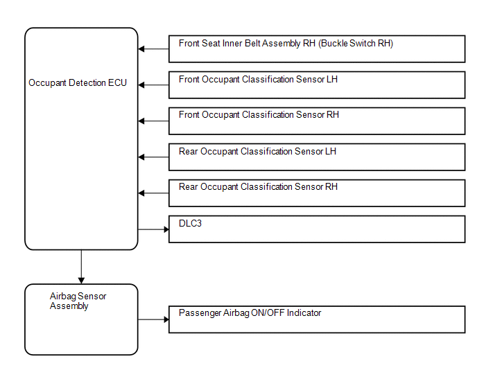
 System Description
SYSTEM DESCRIPTION
1. FRONT PASSENGER OCCUPANT CLASSIFICATION SYSTEM
(a) General Description
(1) The front passenger occupant detection ECU determines whether the front passenger
seat is occupied ...
 Diagnosis System
DIAGNOSIS SYSTEM
1. CHECK DLC3
(a) The vehicle's ECU uses the ISO 9141-2 for communication protocol. The terminal
arrangement of the DLC3 complies with SAE J1962 and matches the ISO 15765-4 fo ...
Other materials:
Installation
INSTALLATION
PROCEDURE
1. INSTALL REAR BUMPER ASSEMBLY
(a) Using an engine lifter or equivalent, engage the 2 pins to install the rear
bumper assembly as shown in the illustration.
Text in Illustration
*a
Pin
-
-
NOTICE:
Using pl ...
Lock Switch Circuit
WIRING DIAGRAM
PROCEDURE
1.
CHECK REAR DIFFERENTIAL LOCK INDICATOR LIGHT
(a) Turn the ignition switch to ON.
(b) for 4WD:
Finish switching to L4.
(c) Check the rear differential lock indicator light.
(d) Press the differential lock switch.
(e) After 60 secon ...
Inspection
INSPECTION
PROCEDURE
1. INSPECT OUTER MIRROR LH
(a) Check the outer mirror heater operation.
Text in Illustration
*a
Component without harness connected
(Outer Mirror LH)
(1) Measure the resistance according to the value(s) ...
