Toyota Tacoma (2015-2018) Service Manual: System Diagram
SYSTEM DIAGRAM
 Precaution
PRECAUTION
1. EXPRESSIONS OF IGNITION SWITCH
The type of ignition switch used on this model differs depending on the specifications
of the vehicle. The expressions listed in the table below are us ...
 How To Proceed With Troubleshooting
CAUTION / NOTICE / HINT
HINT:
Use this procedure to troubleshoot the seat heater system.
*: Use the Techstream.
PROCEDURE
1.
VEHICLE BROUGHT TO WORKSHOP
...
Other materials:
Data List / Active Test
DATA LIST / ACTIVE TEST
HINT:
By accessing the Data List displayed by the Techstream, you can check values
of switches and sensors without removing any parts. Reading the Data List as the
first step of troubleshooting is one method to shorten diagnostic time.
1. DATA LIST FOR OCCUPANT DETECTI ...
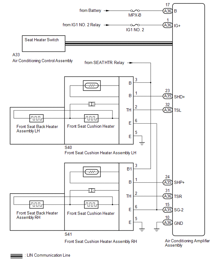
System Diagram
SYSTEM DIAGRAM
Communication Table
Transmitting ECU
Receiving ECU
Signal
Communication Method
Power Window Regulator Master Switch Assembly
Power Window Regulator Motor Assembly (for Driver Door)
Power Window ...
Engine Immobiliser System Circuit Short to Battery (B279A12)
DESCRIPTION
When the communication line (IMI - EFIO) between the ECM and certification ECU
(smart key ECU assembly) is stuck high, the ECM stores this DTC.
DTC Code
DTC Detection Condition
Trouble Area
DTC Output Confirmation Operation
...
