Toyota Tacoma (2015-2018) Service Manual: System Diagram
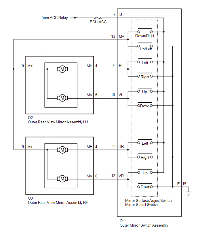
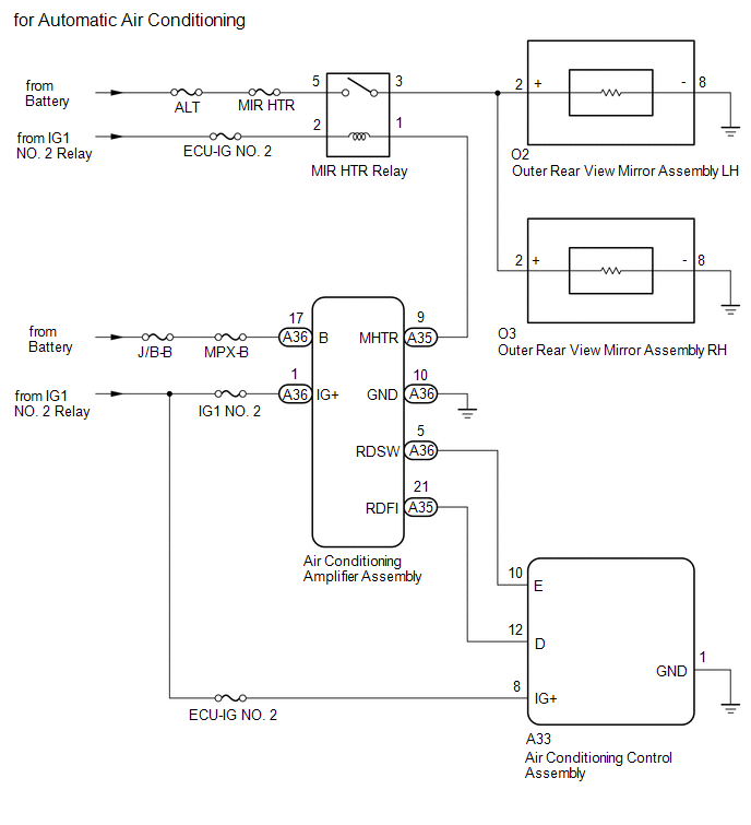
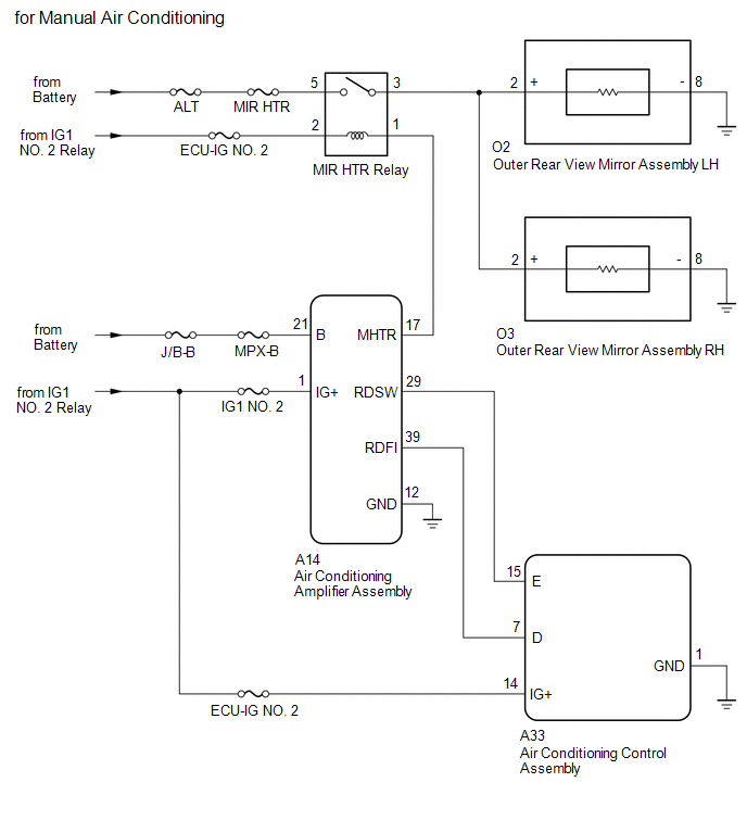
SYSTEM DIAGRAM
 System Description
SYSTEM DESCRIPTION
1. FUNCTION OF MAIN COMPONENTS
Component
Function
Vertical mirror motor
Moves the mirror surface vertically in accordance with th ...
 Operation Check
OPERATION CHECK
1. CHECK REMOTE CONTROL MIRROR FUNCTION
(a) Turn the ignition switch to ON.
(b) With L on the mirror select switch selected, check that the outer rear view
mirror assembly LH surf ...
Other materials:
Security Horn Assembly
Components
COMPONENTS
ILLUSTRATION
Inspection
INSPECTION
PROCEDURE
1. INSPECT SECURITY HORN ASSEMBLY
(a) Check the operation.
(1) Apply battery voltage and check operation of the security horn assembly.
OK:
Measurement Condition
Spe ...
Certification Ecu
Components
COMPONENTS
ILLUSTRATION
Installation
INSTALLATION
PROCEDURE
1. INSTALL CERTIFICATION ECU (SMART KEY ECU ASSEMBLY)
(a) Install the certification ECU (smart key ECU assembly) with the 2 nuts.
Torque:
6.5 N·m {66 kgf·cm, 58 in·lbf}
(b) Engage the clamp to install the wire ...
Tire information
Typical tire symbols
1. Tire size
2. DOT and Tire Identification Number (TIN)
3. Location of treadwear indicators
4. Tire ply composition and materials
Plies are layers of rubber-coated parallel cords. Cords are the strands which
form the plies in a tire.
5. Uniform tire quality grading
F ...
