Toyota Tacoma (2015-2018) Service Manual: System Diagram
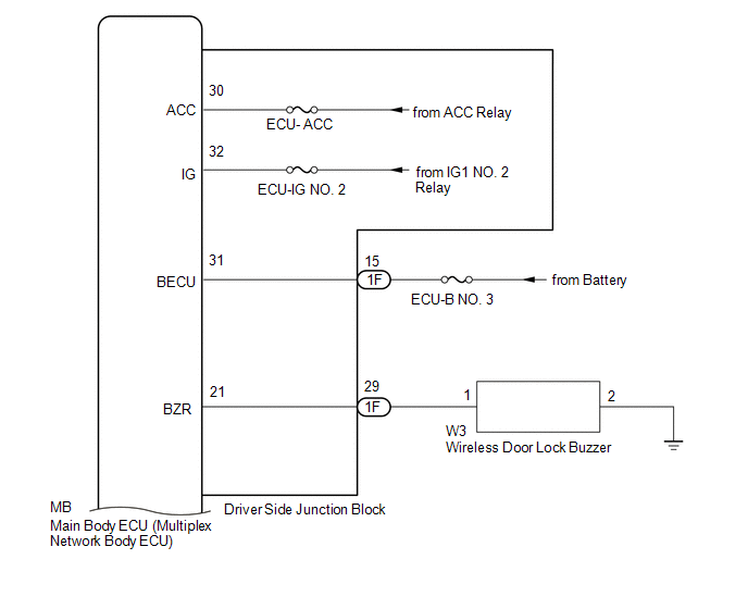
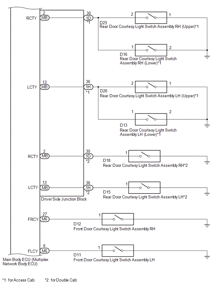
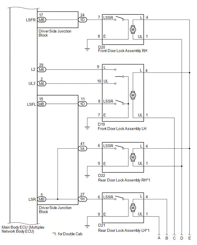
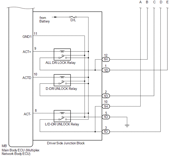
SYSTEM DIAGRAM
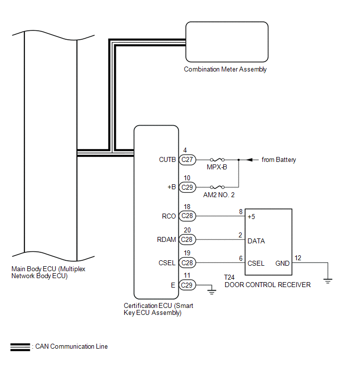
 Communication Table
|
Transmitting ECU (Transmitter) |
Receiving ECU (Receiver) |
Signal |
Line |
|---|---|---|---|
|
Certification ECU (Smart Key ECU Assembly) |
Main Body ECU (Multiplex Network Body ECU) |
|
CAN |
|
Main Body ECU (Multiplex Network Body ECU) |
Combination Meter Assembly |
Wireless door lock hazard warning light request signal |
CAN |
 System Description
SYSTEM DESCRIPTION
1. WIRELESS DOOR LOCK CONTROL SYSTEM
The wireless door lock control system can be used to lock and unlock all doors
from a distance. The system is controlled by an electrical ke ...
 Customize Parameters
CUSTOMIZE PARAMETERS
PROCEDURE
1. CUSTOMIZE WIRELESS DOOR LOCK CONTROL SYSTEM (w/ Smart Key System)
HINT:
The following items can be customized.
NOTICE:
When the customer requests a chan ...
Other materials:
Front seats
Bench type seat
Seat position adjustment lever
Separated type seats
Seat position adjustment lever
Driver’s seat lumbar support adjustment
knob (if equipped)
Seatback angle adjustment lever ...
Inspection
INSPECTION
PROCEDURE
1. INSPECT WINDSHIELD WIPER SWITCH ASSEMBLY
(a) Check the resistance.
Text in Illustration
*a
Component without harness connected
(Windshield Wiper Switch Assembly)
(1) Measure the resistance according ...
Installation
INSTALLATION
PROCEDURE
1. INSTALL OIL COOLER TUBE
(a) Install the oil cooler tube to the vehicle body with the 2 bolts.
Torque:
28 N·m {286 kgf·cm, 21 ft·lbf}
2. INSTALL NO. 4 OIL COOLER INLET HOSE AND NO. 4 OIL COOLER OUTLET HOSE
NOTICE:
When connecting the hoses to the tube, su ...
