Toyota Tacoma (2015-2018) Service Manual: System Diagram
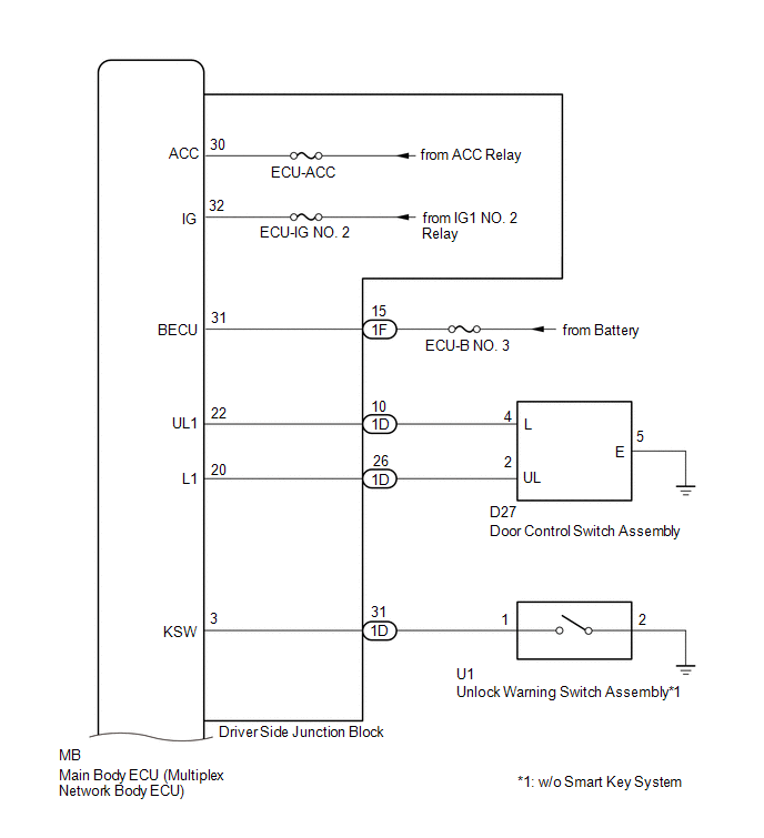
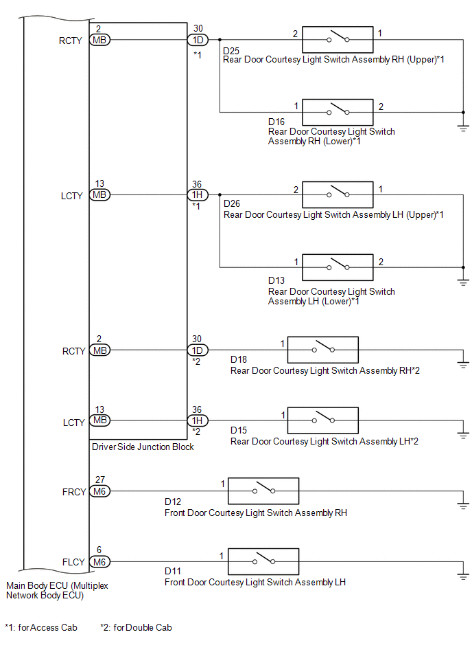
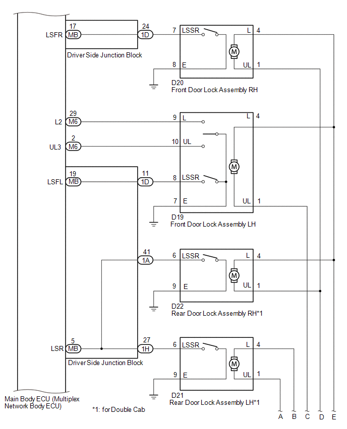
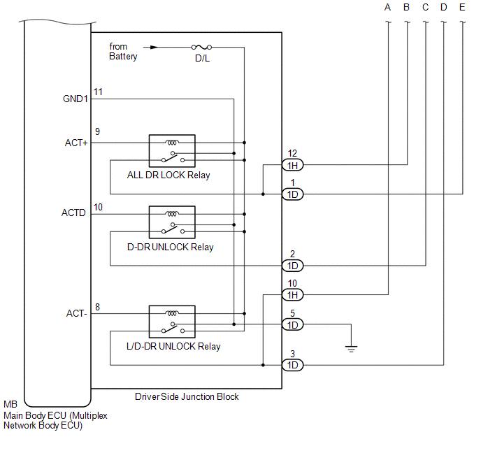
SYSTEM DIAGRAM
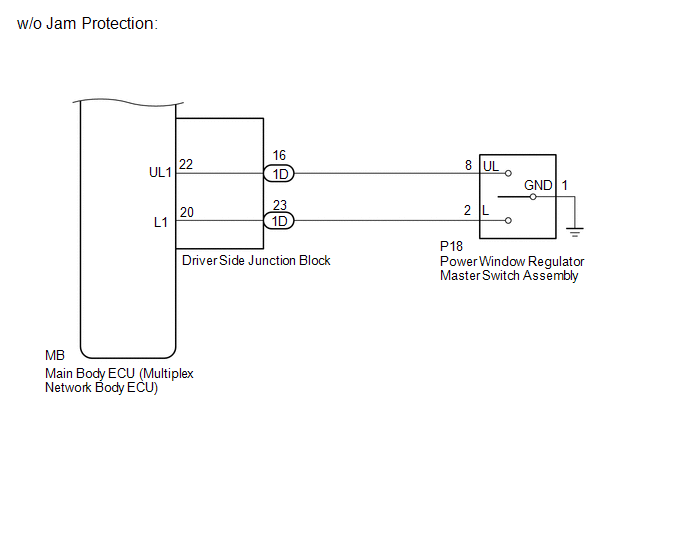
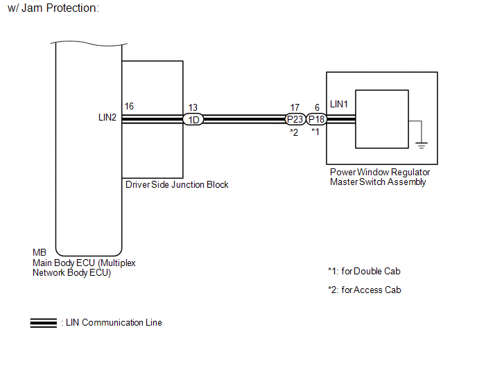 Communication Table
|
Sender |
Receiver |
Signal |
Communication Method |
|---|---|---|---|
|
Power window regulator master switch assembly*1 |
Main Body ECU (Multiplex Network Body ECU) |
Door control switch signal |
LIN |
- *1: w/ Jam Protection
 System Description
SYSTEM DESCRIPTION
1. POWER DOOR LOCK CONTROL SYSTEM DESCRIPTION
(a) The power door lock system locks/unlocks all the doors.
The main body ECU (multiplex network body ECU) receives lock/unlock requ ...
 Customize Parameters
CUSTOMIZE PARAMETERS
1. CUSTOMIZE POWER DOOR LOCK CONTROL SYSTEM
HINT:
The following items can be customized.
NOTICE:
When the customer requests a change in a function, first make sure th ...
Other materials:
Components
COMPONENTS
ILLUSTRATION
*1
CHARCOAL CANISTER ASSEMBLY
*2
CHARCOAL CANISTER FUEL HOSE
*3
CHARCOAL CANISTER LEAK DETECTION PUMP SUB-ASSEMBLY
*4
FUEL TANK VENT HOSE
*5
FUEL TANK ...
Antenna Coil Open / Short (B2784)
DESCRIPTION
When an open or short circuit is detected in the antenna coil built into the
transponder key coil, the transponder key ECU assembly stores this DTC.
DTC No.
DTC Detection Condition
Trouble Area
DTC Output Confirmation Operation
...
Fail-safe Chart
FAIL-SAFE CHART
1. FAIL SAFE OPERATION
If there is a problem with any sensor signals or hydraulic brake booster
systems, the skid control ECU prohibits the power supply to the actuator
in the hydraulic brake booster and informs the ECM of VSC system failure.
The hydraulic brake b ...
