Toyota Tacoma (2015-2018) Service Manual: System Diagram
SYSTEM DIAGRAM
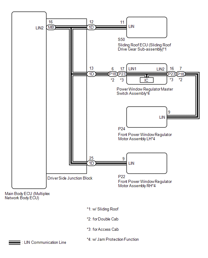
1. DOOR BUS LINES
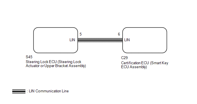
2. CERTIFICATION BUS LINES (w/ Smart Key System)
 System Description
SYSTEM DESCRIPTION
1. LIN COMMUNICATION SYSTEM DESCRIPTION
The LIN communication system is used for communication between the components
in the tables below. If communication cannot be performed t ...
 How To Proceed With Troubleshooting
CAUTION / NOTICE / HINT
HINT:
Use the following procedure to troubleshoot the LIN communication system.
*: Use the Techstream.
PROCEDURE
1.
VEHICLE BROU ...
Other materials:
Removal
REMOVAL
PROCEDURE
1. REMOVE FRONT WIPER ARM HEAD CAP
(a) Using a screwdriver with its tip wrapped in protective tape, disengage
the 3 claws to remove the front wiper arm head cap.
Text in Illustration
*a
Protective Tape
HINT ...
Terminals Of Ecu
TERMINALS OF ECU
1. CHECK DRIVER SIDE JUNCTION BLOCK AND MAIN BODY ECU (MULTIPLEX NETWORK BODY
ECU)
(a) Disconnect the MB main body ECU (multiplex network body ECU) connectors.
(b) Measure the voltage and resistance according to the value(s) in the table
below.
HINT:
Measure the values on ...
Open in ABS Solenoid Relay Circuit (C146E,C146F)
DESCRIPTION
The ABS solenoid relay supplies power to the ABS solenoid and TRAC solenoid.
The solenoid relay is turned on 1.5 seconds after the ignition switch is turned
ON, and is turned off if an open or short in the solenoid is detected by the self
diagnosis performed when the engine starts ...
