Toyota Tacoma (2015-2018) Service Manual: System Diagram
SYSTEM DIAGRAM
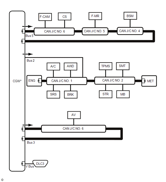
1. OVERALL CAN BUS DIAGRAM
(a) The CAN communication system is composed of 4 buses.
 |
CAN Main Bus Line |
 |
Terminating Resistor |
 |
CAN Branch Line |
* |
Gateway Function Equipped ECU |
.png) |
Bus Monitoring Direction |
- |
- |
|
Bus |
Code |
ECU/Sensor Name |
CAN DTC Storage |
Note |
|---|---|---|---|---|
|
- |
CGW |
Central Gateway ECU (Network Gateway ECU) |
- |
- |
|
V Bus |
DLC3 |
DLC3 |
- |
- |
|
Bus 2 |
ENG |
ECM |
Available |
- |
|
MET |
Combination Meter Assembly |
Available |
- |
|
|
A/C |
Air Conditioning Amplifier Assembly |
Available |
- |
|
|
SMT |
Certification ECU (Smart Key ECU Assembly) |
Available |
|
|
|
MB |
Main Body ECU (Multiplex Network Body ECU) |
Available |
The main body ECU (multiplex network body ECU) is also connected to the LIN communication system. |
|
|
AWD |
4 Wheel Drive Control ECU |
Available |
for 4WD |
|
|
BRK |
Brake Booster Assembly (Skid Control ECU) |
Available |
for Hydraulic Brake Booster |
|
|
Brake Actuator Assembly (Skid Control ECU) |
Available |
for Vacuum Brake Booster |
||
|
TPMS |
Door Control and Tire Pressure Monitoring System Receiver Assembly |
Available |
w/ Tire Pressure Warning System and Tire Inflation Pressure Display Function |
|
|
SRS |
Airbag Sensor Assembly |
- |
- |
|
|
STR |
Spiral Cable with Sensor Sub-assembly |
- |
- |
|
|
CAN J/C NO. 1 |
No. 1 CAN Junction Connector |
- |
- |
|
|
CAN J/C NO. 2 |
No. 2 CAN Junction Connector |
- |
- |
|
|
Bus 3 |
AV |
Navigation Receiver Assembly |
Available |
for Navigation Receiver Type |
|
Radio and Display Receiver Assembly |
Available |
for Radio and Display Type |
||
|
CAN J/C NO. 6 |
No. 6 CAN Junction Connector |
- |
- |
|
|
Bus 5 |
CS |
Clearance Warning ECU Assembly |
Available |
w/ Intuitive Parking Assist System |
|
F-CAM |
Forward Recognition Camera |
Available |
w/ Toyota Safety Sense P |
|
|
F-MR |
Millimeter Wave Radar Sensor Assembly |
- |
w/ Toyota Safety Sense P |
|
|
BSM |
Blind Spot Monitor Sensor LH |
Available |
w/ Blind Spot Monitor System |
|
|
CAN J/C NO. 4 |
No. 4 CAN Junction Connector |
- |
- |
|
|
CAN J/C NO. 5 |
No. 5 CAN Junction Connector |
- |
- |
|
|
CAN J/C NO. 6 |
No. 6 CAN Junction Connector |
- |
- |
 Precaution
PRECAUTION
1. EXPRESSIONS OF IGNITION SWITCH
HINT:
The type of ignition switch used on this model differs according to the specifications
of the vehicle. The expressions listed in the table below ...
 Problem Symptoms Table
PROBLEM SYMPTOMS TABLE
HINT:
Use the table below to help determine the cause of problem symptoms.
If multiple suspected areas are listed, the potential causes of the symptoms
are lis ...
Other materials:
Terminals Of Ecu
TERMINALS OF ECU
1. OCCUPANT DETECTION ECU
Symbols (Terminal No.)
Wiring Color
Terminal Description
Condition
Specification
+B (O5-1) -
GND (O5-3)
R - W-B
Battery
Ignition switch on
...
Cargo Light
Components
COMPONENTS
ILLUSTRATION
Removal
REMOVAL
PROCEDURE
1. REMOVE ROOF HEADLINING ASSEMBLY
for Double Cab:
(See page
)
for Access Cab:
(See page
)
2. REMOVE CARGO LIGHT ASSEMBLY (CENTER STOP LIGHT ASSEMBLY)
(a) Remove the 2 nuts.
...
Removal
REMOVAL
CAUTION / NOTICE / HINT
HINT:
Use the same procedure for the RH and LH sides.
The procedure listed below is for the LH side.
PROCEDURE
1. REMOVE REAR DOOR FRAME GARNISH
(See page )
2. REMOVE REAR DOOR INSIDE HANDLE BEZEL PLUG
(See page )
3. REMOVE REAR ARMREST ...
