Toyota Tacoma (2015-2018) Service Manual: Removal
REMOVAL
CAUTION / NOTICE / HINT
HINT:
- Use the same procedure for the RH and LH sides.
- The procedure listed below is for the LH side.
PROCEDURE
1. REMOVE REAR DOOR FRAME GARNISH
(See page .gif) )
)
2. REMOVE REAR DOOR INSIDE HANDLE BEZEL PLUG
(See page )
3. REMOVE REAR ARMREST BASE UPPER PANEL SUB-ASSEMBLY
(See page )
4. REMOVE REAR DOOR TRIM BOARD SUB-ASSEMBLY
(See page )
5. REMOVE REAR SPEAKER ASSEMBLY
(a) Disconnect the connector.
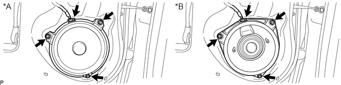 Text in Illustration
|
*A |
w/o Amplifier Box Speaker Assembly |
*B |
w/ Amplifier Box Speaker Assembly |
NOTICE:
Do not touch the cone part of the rear speaker assembly.
(b) Remove the 3 screws and rear speaker assembly.
 Components
COMPONENTS
ILLUSTRATION
...
 Inspection
INSPECTION
PROCEDURE
1. INSPECT REAR SPEAKER ASSEMBLY (w/o Amplifier Box Speaker Assembly)
(a) Measure the resistance according to the value(s) in the table below.
Standard resistance:
...
Other materials:
Front seats
Bench type seat
Seat position adjustment lever
Separated type seats
Seat position adjustment lever
Driver’s seat lumbar support adjustment
knob (if equipped)
Seatback angle adjustment lever ...
Torque Converter Clutch Circuit Short to Ground (P074011)
DESCRIPTION
Shift solenoid valve SL is turned on and off by signals from the ECM to control
the hydraulic pressure acting on the lock-up relay valve, which then controls operation
of the lock-up clutch.
DTC No.
DTC Detection Condition
Trouble Area
SA ...
Cargo Light
Components
COMPONENTS
ILLUSTRATION
Removal
REMOVAL
PROCEDURE
1. REMOVE ROOF HEADLINING ASSEMBLY
for Double Cab:
(See page
)
for Access Cab:
(See page
)
2. REMOVE CARGO LIGHT ASSEMBLY (CENTER STOP LIGHT ASSEMBLY)
(a) Remove the 2 nuts.
...
