Toyota Tacoma (2015-2018) Service Manual: System Diagram
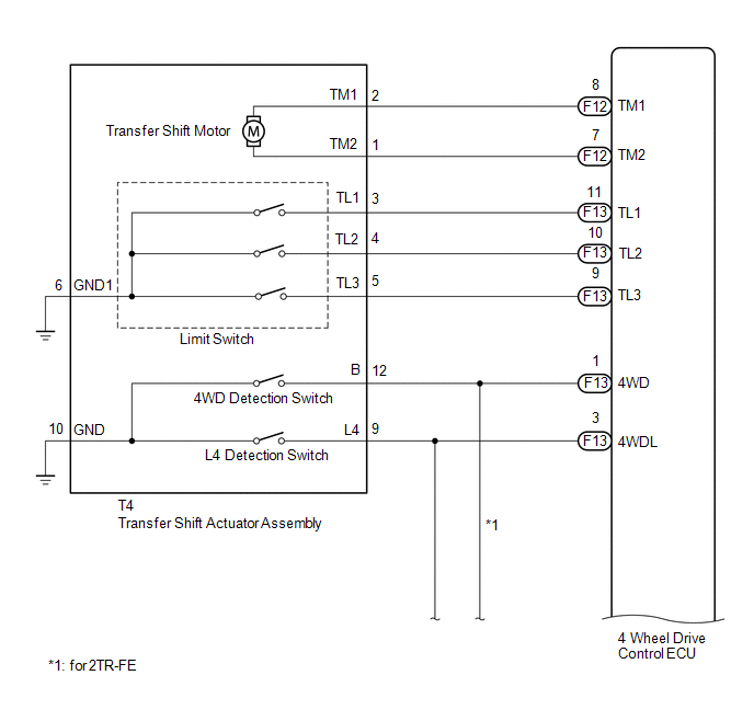
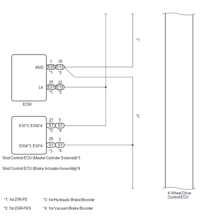
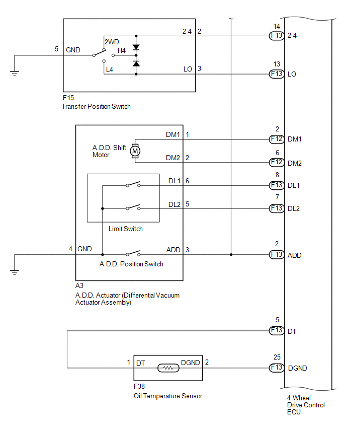
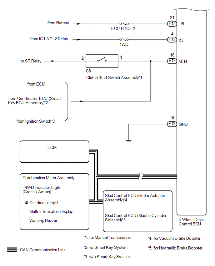
SYSTEM DIAGRAM
|
Transmitting ECU (Transmitter) |
Receiving ECU |
Signal |
Communication Method |
|---|---|---|---|
|
4 wheel drive control ECU |
Skid control ECU (Brake actuator assembly) |
|
CAN communication system |
|
Skid control ECU (Brake actuator assembly) |
4 wheel drive control ECU |
|
CAN communication system |
|
4 wheel drive control ECU |
ECM |
|
CAN communication system |
|
ECM |
4 wheel drive control ECU |
|
CAN communication system |
|
4 wheel drive control ECU |
Combination meter assembly |
|
CAN communication system |
 System Description
SYSTEM DESCRIPTION
1. DESCRIPTION
A part-time 2-speed VF2CM transfer uses a touch select 2-4 and high-low
system, enabling the driver to switch between 2WD, H4 and L4 modes by turning
...
 Diagnosis System
DIAGNOSIS SYSTEM
1. DESCRIPTION
The 4 wheel drive control ECU records DTCs when the ECU detects a malfunction
in the ECU itself or in system circuits.
The DTCs can be read through the DLC3 of the ...
Other materials:
Door Courtesy Switch Circuit
DESCRIPTION
The main body ECU (multiplex network Body ECU) receives a door open or closed
signal from each door courtesy light switch.
WIRING DIAGRAM
CAUTION / NOTICE / HINT
NOTICE:
Recognition code registration is necessary when replacing the main body
ECU (multiplex network bo ...
Diagnostic Trouble Code Chart
DIAGNOSTIC TROUBLE CODE CHART
Sliding Roof (Sliding Roof ECU (Sliding Roof Drive Gear Sub-assembly))
DTC Code
Detection Item
See page
B2341
Sensor (Motor) Failure
B2342
Switch Failure
...
Inspection
INSPECTION
PROCEDURE
1. INSPECT CENTER STOP LIGHT ASSEMBLY (for LED Type Stop Light)
(a) Check the illuminates.
(1) Apply battery voltage to the connector and check the light illumination
condition.
Text in Illustration
*a
Component without ...
