Toyota Tacoma (2015-2018) Service Manual: Parts Location
PARTS LOCATION
ILLUSTRATION
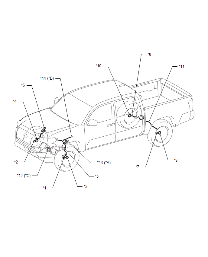
|
*A |
for Automatic Transmission |
*B |
for Manual Transmission |
|
*C |
for 4WD |
- |
- |
|
*1 |
FRONT SPEED SENSOR LH |
*2 |
FRONT SPEED SENSOR RH |
|
*3 |
FRONT AXLE WITH ABS ROTOR BEARING ASSEMBLY LH - FRONT SPEED SENSOR ROTOR LH |
*4 |
FRONT AXLE WITH ABS ROTOR BEARING ASSEMBLY RH - FRONT SPEED SENSOR ROTOR RH |
|
*5 |
SKID CONTROL SENSOR WIRE LH |
*6 |
SKID CONTROL SENSOR WIRE RH |
|
*7 |
REAR SPEED SENSOR LH |
*8 |
REAR SPEED SENSOR RH |
|
*9 |
REAR AXLE HUB AND BEARING ASSEMBLY LH - REAR SPEED SENSOR ROTOR LH |
*10 |
REAR AXLE HUB AND BEARING ASSEMBLY RH - REAR SPEED SENSOR ROTOR RH |
|
*11 |
REAR SKID CONTROL SENSOR WIRE |
*12 |
DIFFERENTIAL VACUUM ACTUATOR ASSEMBLY - A.D.D. POSITION SWITCH |
|
*13 |
PARK/NEUTRAL POSITION SWITCH |
*14 |
BACK-UP LIGHT SWITCH ASSEMBLY |
ILLUSTRATION
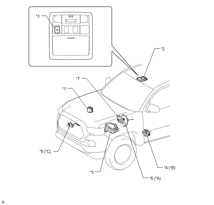
|
*A |
for 2GR-FKS |
*B |
for 4WD |
|
*C |
w/ Toyota Safety Sense P |
- |
- |
|
*1 |
BRAKE ACTUATOR ASSEMBLY - SKID CONTROL ECU |
*2 |
ROOF CONSOLE BOX ASSEMBLY |
|
*3 |
VSC OFF SWITCH |
*4 |
TRANSFER SHIFT ACTUATOR ASSEMBLY |
|
*5 |
ENGINE ROOM RELAY BLOCK AND JUNCTION BLOCK - STOP RELAY - ABS NO. 1 FUSE - ABS NO. 2 FUSE - STOP FUSE - ECU-B NO. 2 FUSE |
*6 |
VACUUM WARNING SWITCH ASSEMBLY |
|
*7 |
BRAKE MASTER CYLINDER SUB-ASSEMBLY - BRAKE FLUID LEVEL WARNING SWITCH |
*8 |
MILLIMETER WAVE RADAR SENSOR ASSEMBLY |
ILLUSTRATION
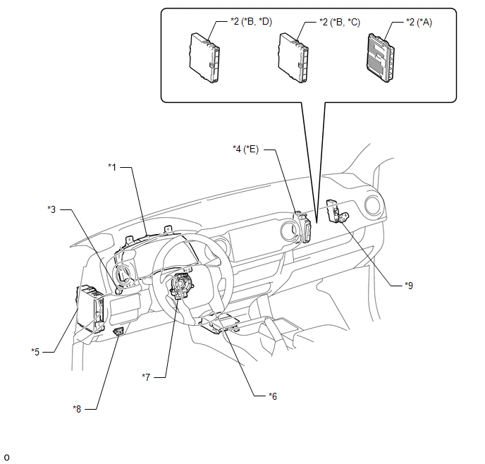
|
*A |
for 2GR-FKS |
*B |
for 2TR-FE |
|
*C |
for Automatic Transmission |
*D |
for Manual Transmission |
|
*E |
for 4WD |
- |
- |
|
*1 |
COMBINATION METER ASSEMBLY |
*2 |
ECM |
|
*3 |
STOP LIGHT SWITCH ASSEMBLY |
*4 |
4 WHEEL DRIVE CONTROL ECU |
|
*5 |
DRIVER SIDE JUNCTION BLOCK - ECU-IG NO. 3 FUSE - IG1 NO. 1 FUSE - A/BAG FUSE - BKUP LP NO. 3 FUSE |
*6 |
AIRBAG SENSOR ASSEMBLY - YAW RATE AND ACCELERATION SENSOR |
|
*7 |
SPIRAL CABLE WITH SENSOR SUB-ASSEMBLY |
*8 |
DLC3 |
|
*9 |
NETWORK GATEWAY ECU |
- |
- |

 Precaution
PRECAUTION
1. IGNITION SWITCH EXPRESSION
(a) The type of ignition switch used on this model differs depending on the specifications
of the vehicle.
The expressions listed in the table below are u ...
Other materials:
Child restraint systems
A child restraint system for a small child or baby must itself be properly
restrained on the seat with the lap portion of the lap/shoulder belt.
The laws of all 50 states of the U.S.A. and Canada now require the use of child
restraint systems.
Points to remember
Studies have shown that instal ...
Power Source Circuit
DESCRIPTION
This circuit provides power to operate the forward recognition camera.
WIRING DIAGRAM
CAUTION / NOTICE / HINT
NOTICE:
Inspect the fuses for circuits related to this system before performing the following
inspection procedure.
PROCEDURE
1.
CHECK HARNESS A ...
Removal
REMOVAL
PROCEDURE
1. REMOVE NO. 2 ENGINE UNDER COVER SUB-ASSEMBLY (w/ Off Road Package)
2. REMOVE NO. 1 ENGINE UNDER COVER SUB-ASSEMBLY
3. DRAIN ENGINE COOLANT
4. REMOVE RADIATOR GRILLE
(See page )
5. REMOVE EXHAUST MANIFOLD SUB-ASSEMBLY RH
(See page )
6. REMOVE NO. 2 OIL COOLER INLET ...
