Toyota Tacoma (2015-2018) Service Manual: Status Signal Circuit
DESCRIPTION
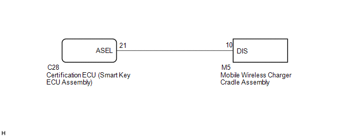
This circuit sends a smart key system status signal from the certification ECU (smart key ECU assembly) to the mobile wireless charger cradle assembly. Based on this signal, the mobile wireless charger cradle assembly suspends or resumes wireless charging.
WIRING DIAGRAM
CAUTION / NOTICE / HINT
NOTICE:
Before replacing the certification ECU (smart key ECU assembly), refer to the
Registration ( .gif) ).
).
PROCEDURE
|
1. |
INSPECT MOBILE WIRELESS CHARGER CRADLE ASSEMBLY |
|
(a) Measure the voltage according to the value(s) in the table below. Text in Illustration
Standard Voltage:
HINT:
|
|
| OK | .gif) |
PROCEED TO NEXT SUSPECTED AREA SHOWN IN PROBLEM SYMPTOMS TABLE |
|
.gif)
|
2. |
CHECK HARNESS AND CONNECTOR (MOBILE WIRELESS CHARGER CRADLE ASSEMBLY - CERTIFICATION ECU (SMART KEY ECU ASSEMBLY)) |
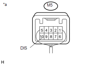
(a) Disconnect the M5 mobile wireless charger cradle assembly connector.
(b) Disconnect the C28 certification ECU (smart key ECU assembly) connector.
(c) Measure the resistance according to the value(s) in the table below.
Standard Resistance:
|
Tester Connection |
Condition |
Specified Condition |
|---|---|---|
|
M5-10 (DIS) - C28-21 (ASEL) |
Always |
Below 1 Ω |
|
M5-10 (DIS) - Body ground |
Always |
10 kΩ or higher |
| OK | |
REPLACE CERTIFICATION ECU (SMART KEY ECU ASSEMBLY) |
| NG | |
REPAIR OR REPLACE HARNESS OR CONNECTOR |
 Main Switch Signal Circuit
DESCRIPTION
When the wireless charger main switch (mobile wireless charger switch) is turned
on, this circuit sends an on signal to the mobile wireless charger cradle assembly
using the power sup ...
 Wireless Charger Illumination Circuit
DESCRIPTION
When the light control switch is turned to the tail or head position, this circuit
sends an illumination signal to the mobile wireless charger cradle assembly. Based
on this signal, t ...
Other materials:
Pattern Select Switch
Components
COMPONENTS
ILLUSTRATION
Removal
REMOVAL
PROCEDURE
1. REMOVE INSTRUMENT PANEL LOWER CENTER FINISH PANEL
(See page )
2. REMOVE PATTERN SELECT SWITCH ASSEMBLY
(a) Detach the 2 claws to remove the pattern select switch assembly from
the instrument panel lower c ...
Precaution
PRECAUTION
1. IGNITION SWITCH EXPRESSIONS
(a) The type of ignition switch used on this model differs according to the specifications
of the vehicle. The expressions listed in the table below are used in this section.
Expression
Ignition Switch (Position)
Engine ...
Removal
REMOVAL
PROCEDURE
1. REMOVE MILLIMETER WAVE RADAR WIRE
(a) for Type A:
(1) Disconnect the 2 connectors.
(2) Using a clip remover, disengage the 4 clamps to remove the millimeter
wave radar wire.
(b) for Type B:
(1) Disc ...
