Toyota Tacoma (2015-2018) Service Manual: Side Turn Signal Light Assembly
Components
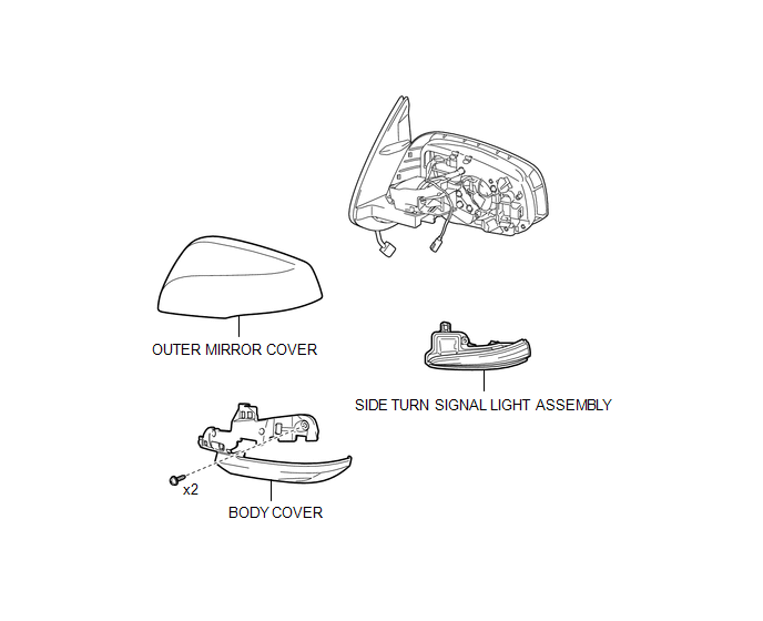
COMPONENTS
ILLUSTRATION
Removal
REMOVAL
CAUTION / NOTICE / HINT
HINT:
- Use the same procedure for both the RH and LH sides.
- The procedure described below is for the LH side.
PROCEDURE
1. REMOVE OUTER REAR VIEW MIRROR ASSEMBLY
(See page .gif) )
)
2. REMOVE OUTER MIRROR COVER
3. REMOVE SIDE TURN SIGNAL LIGHT ASSEMBLY
|
(a) Remove the 2 screws. |
|
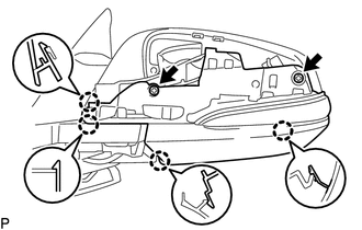
(b) Disengage the 4 claws to separate the body cover with side turn signal light assembly.
|
(c) Disengage the guide to separate the wire harness. |
|
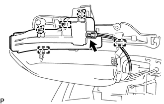
(d) Disconnect the connector to remove the body cover with side turn signal light assembly.
(e) Disengage the 2 claws and 2 guides to remove the side turn signal light assembly.
Inspection
INSPECTION
PROCEDURE
1. INSPECT SIDE TURN SIGNAL LIGHT ASSEMBLY LH
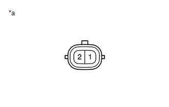
(a) Check the illuminates.
|
(1) Apply battery voltage to the connector and check the light illumination condition. Text in Illustration
OK:
If the result is not as specified, replace the side turn signal light assembly LH. |
|
2. INSPECT SIDE TURN SIGNAL LIGHT ASSEMBLY RH
(a) Check the illuminates.
|
(1) Apply battery voltage to the connector and check the light illumination condition. Text in Illustration
OK:
If the result is not as specified, replace the side turn signal light assembly RH. |
|
Installation
INSTALLATION
CAUTION / NOTICE / HINT
HINT:
- Use the same procedure for both the LH and RH sides.
- The procedure described below is for the LH side.
PROCEDURE
1. INSTALL SIDE TURN SIGNAL LIGHT ASSEMBLY
(a) Engage the 2 guides and 2 claws to install the side turn signal light assembly.
(b) Connect the connector.
(c) Engage the clamp to install the wire harness.
(d) Engage the 4 claws to install the body cover with side turn signal light assembly.
(e) Install the 2 screws.
2. INSTALL OUTER MIRROR COVER
.gif)
3. INSTALL OUTER REAR VIEW MIRROR ASSEMBLY
(See page )
 Room Light Assembly
Components
COMPONENTS
ILLUSTRATION
Removal
REMOVAL
PROCEDURE
1. REMOVE NO. 1 ROOM LIGHT ASSEMBLY
(a) Using a screwdriver with its tip wrapped in protective tape, disengage
...
 Stop Light Switch
Components
COMPONENTS
ILLUSTRATION
Inspection
INSPECTION
PROCEDURE
1. INSPECT STOP LIGHT SWITCH
(a) Check the resistance.
(1) Measure the resistance using an ohmmeter, and check the re ...
Other materials:
Vehicle Speed Sensor Circuit (C1AA3)
DESCRIPTION
The forward recognition camera receives vehicle speed signals from the skid control
ECU. If the skid control ECU receives a vehicle speed sensor malfunction signal,
it informs the forward recognition camera via CAN communication, and DTC C1AA3 is
stored.
DTC No.
...
Dtc Check / Clear
DTC CHECK / CLEAR
CHECK DTC
(a) Connect the Techstream to the DLC3.
(b) Turn the ignition switch to ON.
(c) Turn the Techstream on.
(d) Enter the following menus: Chassis / LKA/LDA / Trouble Codes.
(e) Check for DTCs.
Click here
CLEAR DTC
(a) Connect the Techstream to the DLC3.
(b) Turn ...
Installation
INSTALLATION
PROCEDURE
1. INSTALL PARK/NEUTRAL POSITION SWITCH
HINT:
Make sure that the manual valve lever shaft has not been rotated prior to installing
the park/neutral position switch as the detent spring may become detached from the
manual valve lever shaft.
(a) Clean the bolt and bolt ...
