Toyota Tacoma (2015-2018) Service Manual: Short in GPS Antenna (B15C0,B15C1)
DESCRIPTION
These DTCs are stored when a malfunction occurs in the navigation antenna assembly.
|
DTC No. |
DTC Detection Condition |
Trouble Area |
|---|---|---|
|
B15C0 |
Navigation antenna error |
|
|
B15C1 |
Error of the power source to the navigation antenna |
CAUTION / NOTICE / HINT
NOTICE:
Check that the navigation antenna assembly cable is properly installed and does
not have any sharp bends, pinching or loose connections before performing following
inspection procedure (See page .gif) ).
).
PROCEDURE
|
1. |
CHECK DTC |
(a) Clear the DTCs (See page ).
(b) Recheck for DTCs and check that no DTCs are output.
OK:
No DTCs are output.
| OK | .gif) |
USE SIMULATION METHOD TO CHECK |
|
.gif)
|
2. |
INSPECT NAVIGATION ANTENNA ASSEMBLY |
|
(a) Remove the navigation antenna assembly (See page
|
|
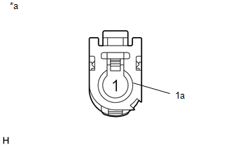
(b) Measure the resistance according to the value(s) in the table below.
Standard Resistance:
|
Tester Connection |
Condition |
Specified Condition |
|---|---|---|
|
1 - 1a |
Always |
50 to 500 Ω |
|
*a |
Component without harness connected (Navigation Antenna Assembly) |
| OK | |
REPLACE RADIO AND DISPLAY RECEIVER ASSEMBLY |
| NG | |
REPLACE NAVIGATION ANTENNA ASSEMBLY |
 AV Signal Stoppage (Low Battery Voltage) (B158F)
DESCRIPTION
This DTC is stored when a video or audio signal is interrupted due to battery
voltage input to the radio and display receiver assembly dropping temporarily.
DTC Code
...
 Speaker Output Short (B15C3)
DESCRIPTION
This DTC is stored when a malfunction occurs in the speakers.
DTC No.
DTC Detection Condition
Trouble Area
B15C3
A short is d ...
Other materials:
Check Bus 3 Lines for Short Circuit
DESCRIPTION
There may be a short circuit between the CAN main bus lines and/or CAN branch
lines when the resistance between terminals 6 (CA3H) and 21 (CA3L) of the central
gateway ECU (network gateway ECU) is below 54 Ω.
Detection Item
Trouble Area
Resis ...
How To Proceed With Troubleshooting
CAUTION / NOTICE / HINT
HINT:
Use the following procedure to troubleshoot the LIN communication system.
*: Use the Techstream.
PROCEDURE
1.
VEHICLE BROUGHT TO WORKSHOP
NEXT
...
Installation
INSTALLATION
PROCEDURE
1. INSTALL LOWER NO. 1 INSTRUMENT PANEL AIRBAG ASSEMBLY
(a) Connect the airbag connector.
NOTICE:
When handling the airbag connector, take care not to damage the airbag
wire harness.
(b) Push in the airbag conn ...
