Toyota Tacoma (2015-2018) Service Manual: Installation
INSTALLATION
PROCEDURE
1. INSTALL LOWER NO. 1 INSTRUMENT PANEL AIRBAG ASSEMBLY
|
(a) Connect the airbag connector. NOTICE: When handling the airbag connector, take care not to damage the airbag wire harness. |
|
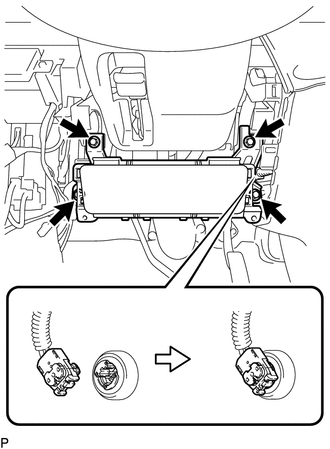
(b) Push in the airbag connector lock to install the airbag connector.
(c) Install the lower No. 1 instrument panel airbag assembly with the 4 bolts.
Torque:
10 N·m {102 kgf·cm, 7 ft·lbf}
2. INSTALL INSTRUMENT PANEL LOWER FINISH PANEL SUB-ASSEMBLY LH
.gif)
3. CONNECT HOOD LOCK CONTROL LEVER SUB-ASSEMBLY
4. INSTALL COWL SIDE TRIM BOARD LH
5. INSTALL FRONT DOOR SCUFF PLATE LH
6. CONNECT CABLE TO NEGATIVE BATTERY TERMINAL
Torque:
5.4 N·m {55 kgf·cm, 48 in·lbf}
NOTICE:
When disconnecting the cable, some systems need to be initialized after the cable is reconnected.
Click here
7. INSPECT SRS WARNING LIGHT
Click here
 Disposal
DISPOSAL
CAUTION / NOTICE / HINT
CAUTION:
Before performing pre-disposal deployment of any SRS part, review and closely
follow all applicable environmental and hazardous material regulations. Pre ...

Other materials:
Removal
REMOVAL
PROCEDURE
1. REMOVE NO. 2 ENGINE UNDER COVER SUB-ASSEMBLY (w/ Off Road Package)
2. REMOVE NO. 1 ENGINE UNDER COVER SUB-ASSEMBLY
3. REMOVE FAN AND GENERATOR V BELT
4. DRAIN POWER STEERING FLUID
5. REMOVE FRONT FENDER APRON UPPER SEAL RH
6. DISCONNECT NO. 1 OIL RESERVOIR TO PUMP ...
Installation
INSTALLATION
CAUTION / NOTICE / HINT
HINT:
Use the same procedures for the RH side and LH side.
The procedures listed below are for the LH side.
When installing a roof drip side moulding clip, heat the vehicle body
and clip using a heat light.
When installing the moulding, ...
Installation
INSTALLATION
CAUTION / NOTICE / HINT
HINT:
Use the same procedure for both the LH and RH sides.
The procedure described below is for the LH side.
PROCEDURE
1. INSTALL FOG LIGHT ASSEMBLY
(a) Engage the 2 guides to install the fog light assembly.
(b) Install the screw.
(c) Co ...
