Toyota Tacoma (2015-2018) Service Manual: Security Horn Assembly
Components
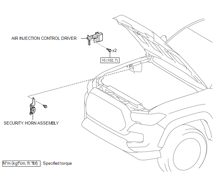
COMPONENTS
ILLUSTRATION
Inspection
INSPECTION
PROCEDURE
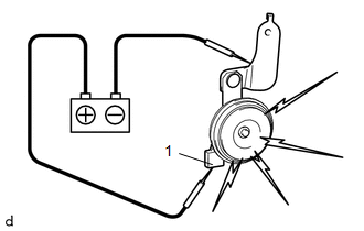
1. INSPECT SECURITY HORN ASSEMBLY
|
(a) Check the operation. (1) Apply battery voltage and check operation of the security horn assembly. OK:
If the result is not as specified, replace the security horn assembly. |
|
Removal
REMOVAL
PROCEDURE
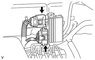
1. REMOVE AIR INJECTION CONTROL DRIVER (for 2TR-FE)
|
(a) Disconnect the 2 connectors. |
|
|
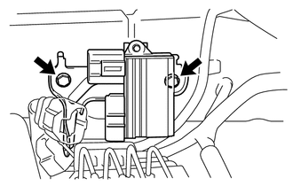
(b) Remove the 2 bolts and air injection control driver. |
|
2. REMOVE SECURITY HORN ASSEMBLY
|
(a) Disconnect the connector. |
|
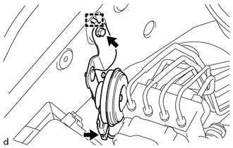
(b) Remove the bolt.
(c) Disengage the guide to remove the security horn assembly.
Installation
INSTALLATION
PROCEDURE
1. INSTALL SECURITY HORN ASSEMBLY
(a) Engage the guide to install the security horn assembly.
(b) Install the bolt.
(c) Connect the connector.
2. INSTALL AIR INJECTION CONTROL DRIVER (for 2TR-FE)
(a) Install the air injection control driver with the 2 bolts.
Torque:
10 N·m {102 kgf·cm, 7 ft·lbf}
(b) Connect the 2 connectors.
 Engine Hood Courtesy Switch
Components
COMPONENTS
ILLUSTRATION
Inspection
INSPECTION
PROCEDURE
1. INSPECT HOOD COURTESY SWITCH (HOOD LOCK ASSEMBLY)
(a) Check the resistance.
(1) Measure the resistance ac ...

Other materials:
AVC-LAN Circuit
DESCRIPTION
Each unit of the navigation system connected to the AVC-LAN (communication bus)
transfers the switch signals using the AVC-LAN.
If a short to +B or short to ground occurs in the AVC-LAN, the navigation system
will not function normally because communication is not possible.
WIRING ...
Reassembly
REASSEMBLY
PROCEDURE
1. INSPECT CENTER NO. 2 SUPPORT BEARING ASSEMBLY
(a) When turning the center No. 2 support bearing assembly with your hand, check
that it turns smoothly without catching and that there are no cracks or damage.
If there are any defects, replace it.
2. INSTALL CENTER NO. ...
ECM Communication Circuit Malfunction (C1203)
DESCRIPTION
The circuit is used to send TRAC and VSC control information from the skid control
ECU (brake actuator assembly) to the ECM, and engine control information from the
ECM to the skid control ECU (brake actuator assembly) through the CAN communication
system.
for 4WD or w/ Rear Diff ...
