Toyota Tacoma (2015-2018) Service Manual: Replacement
REPLACEMENT
PROCEDURE
1. RECOVER REFRIGERANT FROM REFRIGERATION SYSTEM
(a) Start the engine.
(b) Operate the cooler compressor under the conditions shown below:
|
Item |
Condition |
|---|---|
|
Engine Speed |
Idling |
|
Operating Time |
3 minutes or more |
|
A/C Switch Status |
On |
|
Blower Switch Status |
HI |
|
Set Temperature |
MAX COOL |
This causes most of the compressor oil from the various components of the A/C system to collect in the A/C compressor.
NOTICE:
It is not necessary to operate the cooler compressor if the A/C does not operate because of compressor lock, etc.
(c) Stop the engine.
(d) Recover the refrigerant from the A/C system using a refrigerant recovery unit.
NOTICE:
Be sure to use a refrigerant recovery unit that is compatible with HFO-1234yf (R1234yf) systems.
HINT:
Use the refrigerant recovery unit in accordance with the manufacturer's instruction manual.
2. CHARGE AIR CONDITIONING SYSTEM WITH REFRIGERANT
HINT:
Charge refrigerant in accordance with the equipment manual.
(a) Perform vacuum purging using a refrigerant recover unit.
NOTICE:
Be sure to use a refrigerant recovery unit that is compatible with HFO-1234yf (R1234yf) systems.
(b) Charge refrigerant HFO-1234yf (R1234yf).
Standard:
480 to 540 g (16.93 to 19.05 oz.)
NOTICE:
Make sure the amount of refrigerant is within 30 g of the specified amount.
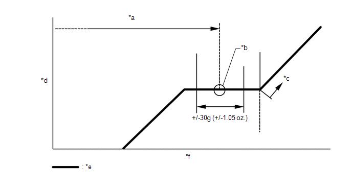 Text in Illustration
|
*a |
Amount to be charged |
*b |
Mean value in proper range |
|
*c |
Overcharged |
*d |
Pressure |
|
*e |
Sub-cool system |
*f |
Refrigerant amount |
NOTICE:
Do not operate the cooler compressor before charging refrigerant as the cooler compressor will not work properly without any refrigerant, and will overheat.
3. WARM UP ENGINE
(a) Warm up the engine at less than 1640 rpm for 2 minutes or more after charging the refrigerant.
NOTICE:
Be sure to warm up the compressor by turning the A/C switch on after removing and installing the cooler refrigerant lines (including the compressor) to prevent damage to the compressor.
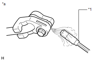
4. INSPECT FOR REFRIGERANT LEAK
(a) After recharging the refrigerant, check for refrigerant gas leakage using a gas leak detector.
HINT:
Be sure to use a gas leak detector that is compatible with HFO-1234yf (R1234yf) systems.
(1) Perform the operation observing the following instructions:
- Stop the engine.
- Secure good ventilation (the gas leak detector may react to volatile gases other than refrigerant, such as evaporated gasoline or exhaust gas).
- Repeat the test 2 or 3 times.
- Make sure that some refrigerant remains in the refrigeration system.
HINT:
When the compressor is off: approximately 392 to 588 kPa (4.0 to 6.0 kgf/cm2, 57 to 85 psi).
|
(2) Using a gas leak detector, check the refrigerant line for leakage. |
|
(3) If a gas leak is not detected from the drain hose, remove the blower motor control (blower resistor) from the cooling unit. Insert the sensor of the gas leak detector into the unit and check for gas leakage.
(4) Disconnect the pressure switch connector and wait for approximately 20 minutes. Bring the gas leak detector close to the pressure switch and check for gas leakage.
Text in Illustration|
*1 |
Gas Leak Detector |
|
*a |
Check for Leakage |
 Precaution
PRECAUTION
1. PRECAUTIONS FOR REFRIGERANT HFO-1234yf (R1234yf)
(a) Compatibility
(1) The parts used in the refrigerant cycle, the compressor oil, etc. of the
HFO-1234yf (R1234yf) system are not c ...

Other materials:
Dtc Check / Clear
DTC CHECK / CLEAR
HINT:
DTCs which are stored in the ECM can be displayed on the Techstream.
The Techstream can display pending DTCs and current DTCs. Some DTCs
are not stored unless a malfunction is detected in consecutive driving cycles.
When a malfunction is detected in o ...
System Diagram
SYSTEM DIAGRAM
This is a detailed diagram related to the main body ECU (multiplex network body
ECU).
Component
Function
Front door outside handle assembly LH
Receives request signals from the certification ECU (smart key ECU assembly) ...
Dtc Check / Clear
DTC CHECK / CLEAR
HINT:
When using the Techstream with the engine switch off to troubleshoot:
Connect the Techstream to the DLC3 and turn a courtesy light switch on and
off at 1.5 second intervals until communication between the Techstream and
vehicle begins.
Refer to the T ...
