Toyota Tacoma (2015-2018) Service Manual: Repair
REPAIR
PROCEDURE
1. STEERING OFF CENTER REPAIR PROCEDURE
(a) Check if the steering wheel is off center.
|
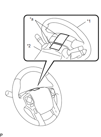
(1) Apply masking tape to the top center of the steering wheel and upper steering column cover. Text in Illustration
|
|
(2) Drive the vehicle in a straight line for 100 m (328 ft.) at a constant speed of 56 km/h (35 mph), and hold the steering wheel to maintain the course.
|
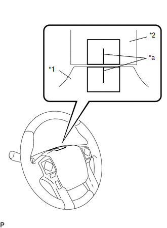
(3) Draw a line on the masking tape as shown in the illustration. Text in Illustration
|
|
(4) Turn the steering wheel to its straight position.
HINT:
Look at the upper surface of the steering wheel, steering spoke and SRS airbag line to find the center position.
|
(5) Draw a new line on the masking tape on the steering wheel as shown in the illustration. Text in Illustration
|
|
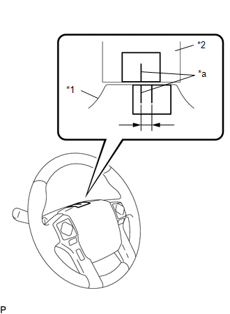
(6) Measure the distance between the 2 lines on the masking tape of the steering wheel.
(7) Convert the measured distance to the steering angle.
HINT:
- Measured distance 1 mm (0.0394 in.) = Steering angle of approximately 1°.
- Make a note of the steering angle.
(b) Adjust the steering angle.
|
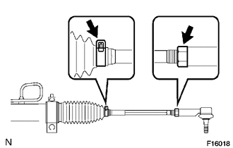
(1) Draw a line on the RH and LH tie rods and on the RH and LH rack ends which can easily be seen. Text in Illustration
|
|
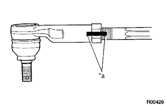
(2) Using a paper gauge, measure the distance from a RH and LH tie rod ends to the rack end screws.
HINT:
- Measure both the RH and LH sides.
- Make a note of the measured values.
|
(3) Remove the RH and LH boot clips from the rack boots. |
|
(4) Loosen the RH and LH lock nuts.
(5) Turn the RH and LH rack ends by the same amount (but in different directions) according to the steering angle.
HINT:
One 360° turn of a rack end (1.5 mm (0.0591 in.) horizontal movement) is equal to a 12° change in steering angle.
(6) Tighten the RH and LH lock nuts.
Torque:
56 N·m {566 kgf·cm, 41 ft·lbf}
NOTICE:
Make sure that the difference in length between the RH and LH tie rod ends and rack end screws is less than 1.5 mm (0.059 in.).
(7) Install the RH and LH boot clips.
 Problem Symptoms Table
PROBLEM SYMPTOMS TABLE
HINT:
Use the table below to help determine the cause of problem symptoms. If multiple
suspected areas are listed, the potential causes of the symptoms are listed in order
...
 Air Conditioning
...
Other materials:
Occupant Classification System Malfunction (B1650/32)
DESCRIPTION
The occupant classification system circuit consists of the airbag sensor assembly
and the occupant classification system.
When the airbag sensor assembly receives signals from the occupant detection
ECU, it determines whether or not the instrument panel passenger without door airba ...
System Diagram
SYSTEM DIAGRAM
Communication Table
Transmitting ECU (Transmitter)
Receiving ECU (Receiver)
Signal
Line
Main body ECU
(Multiplex Network Body ECU)
Combination Meter Assembly
Wireless door lock hazard warnin ...
Parking Brake Switch Circuit
DESCRIPTION
This circuit is from the parking brake switch assembly to the navigation receiver
assembly.
WIRING DIAGRAM
PROCEDURE
1.
CHECK VEHICLE SIGNAL (OPERATION CHECK)
(a) Display the "Vehicle Signal Check Mode" screen (See page
). ...
