Toyota Tacoma (2015-2018) Service Manual: Removal
REMOVAL
PROCEDURE
1. PRECAUTION
NOTICE:
After turning the ignition switch off, waiting time may be required before disconnecting the cable from the negative (-) battery terminal. Therefore, make sure to read the disconnecting the cable from the negative (-) battery terminal notices before proceeding with work.
Click here .gif)
2. DISCONNECT CABLE FROM NEGATIVE BATTERY TERMINAL
NOTICE:
When disconnecting the cable, some systems need to be initialized after the cable is reconnected.
Click here
3. REMOVE HEATED OXYGEN SENSOR
Click here
4. REMOVE TAIL EXHAUST PIPE ASSEMBLY
|
(a) Remove the 2 bolts to separate the tail exhaust pipe assembly. |
|
(b) Disconnect the 4 exhaust pipe supports to remove the tail exhaust pipe assembly.
5. REMOVE CENTER EXHAUST PIPE ASSEMBLY
|
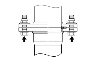
(a) Remove the 2 bolts and 2 compression springs. |
|
.png)
|
(b) Remove the 2 bolts to separate the center exhaust pipe assembly. |
|
.png)
(c) Disconnect the exhaust pipe support to remove the center exhaust pipe assembly.
6. REMOVE CENTER NO. 2 FLOOR HEAT INSULATOR SUB-ASSEMBLY (for 4WD)
|
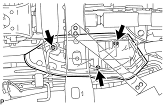
(a) Remove the 3 nuts and center No. 2 floor heat insulator sub-assembly. |
|
7. REMOVE EXHAUST PIPE STOPPER BRACKET (for 4WD)
|
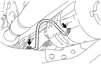
(a) Remove the 2 bolts and exhaust pipe stopper bracket. |
|
8. REMOVE FRONT NO. 2 EXHAUST PIPE ASSEMBLY
|
(a) Remove the 2 nuts to separate the front No. 2 exhaust pipe assembly from the exhaust manifold LH. |
|
.png)
(b) Disconnect the exhaust pipe support to remove the front No. 2 exhaust pipe assembly.
9. REMOVE FRONT EXHAUST PIPE ASSEMBLY
|
(a) Remove the 2 nuts and front exhaust pipe assembly. |
|
.png)
10. REMOVE MONOLITHIC CONVERTER PROTECTOR
|
(a) Remove the bolt and clamp. |
|
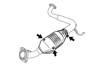
(b) Remove the 2 bolts, 2 nuts and upper monolithic converter protector and lower monolithic converter protector.
 Components
COMPONENTS
ILLUSTRATION
ILLUSTRATION
...
 Installation
INSTALLATION
PROCEDURE
1. REMOVE MONOLITHIC CONVERTER PROTECTOR
(a) Install the upper monolithic converter protector and lower monolithic converter
protector with the 2 bolts and 2 nuts.
Torque: ...
Other materials:
Additional Key cannot be Registered
DESCRIPTION
If additional registration is not possible, a malfunction in the certification
ECU (smart key ECU assembly), engine switch, electrical key transmitter sub-assembly
or steering lock ECU (steering lock actuator or UPR bracket assembly) is suspected.
CAUTION / NOTICE / HINT
NOTICE ...
Vehicle Control History
VEHICLE CONTROL HISTORY
1. Function Overview
(a) The vehicle control history is a function that records control data (record
data) when triggered by specific vehicle behavior. When DTCs are not detected according
to information provided by customers, by checking the vehicle control history, it ...
Inspection
INSPECTION
PROCEDURE
1. INSPECT REAR NO. 2 POWER WINDOW REGULATOR SWITCH ASSEMBLY
*a
Component without harness connected
(Rear No. 2 Power Window Regulator Switch Assembly)
*b
Pull (Close)
*c
Push (Open)
...
