Toyota Tacoma (2015-2018) Service Manual: Components
COMPONENTS
ILLUSTRATION
ILLUSTRATION
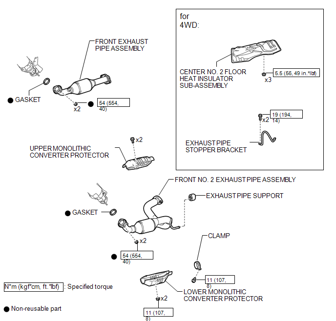
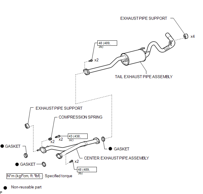
 Exhaust Pipe
...
 Removal
REMOVAL
PROCEDURE
1. PRECAUTION
NOTICE:
After turning the ignition switch off, waiting time may be required before disconnecting
the cable from the negative (-) battery terminal. Therefore, make ...
Other materials:
Blind Spot Monitor Main Switch
Components
COMPONENTS
ILLUSTRATION
Removal
REMOVAL
PROCEDURE
1. REMOVE INSTRUMENT PANEL LOWER CENTER FINISH PANEL
(See page )
2. REMOVE BLIND SPOT MONITOR MAIN SWITCH (WARNING CANCELING SWITCH ASSEMBLY)
(a) Disengage the 2 claws to remove the blind spot monitor main switch ...
Problem Symptoms Table
PROBLEM SYMPTOMS TABLE
HINT:
Use the table below to help determine the cause of problem symptoms.
If multiple suspected areas are listed, the potential causes of the symptoms
are listed in order of probability in the "Suspected Area" column of the
table. Check each sy ...
Check For Intermittent Problems
CHECK FOR INTERMITTENT PROBLEMS
HINT:
Inspect the vehicle ECM using check mode. Intermittent problems are easier to
detect with the Techstream when the ECM is in check mode. In check mode, the ECM
uses 1 trip detection logic, which is more sensitive to malfunctions than normal
mode (default) ...
