Toyota Tacoma (2015-2018) Service Manual: Removal
REMOVAL
PROCEDURE
1. REMOVE FRONT FENDER SEAL LH
|
(a) Remove the 5 clips and front fender seal LH. |
|
2. REMOVE FRONT FENDER SEAL RH
HINT:
Use the same procedure as for the LH side.
3. REMOVE FRONT EXHAUST PIPE ASSEMBLY
|
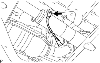
(a) Disengage the 3 clamps to separate the wire harness. |
|
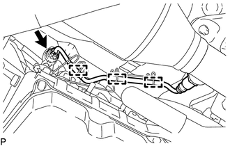
(b) Disconnect the connector.
|
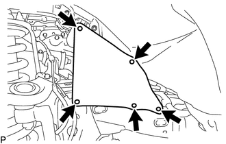
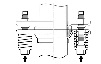
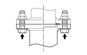
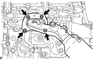
(c) Remove the 2 bolts and 2 compression springs to separate the front exhaust pipe assembly. |
|
|
(d) Remove the 2 nuts and front exhaust pipe assembly. |
|
(e) Remove the 2 gaskets from the front exhaust pipe assembly.
4. REMOVE CENTER NO. 2 FLOOR HEAT INSULATOR SUB-ASSEMBLY (for 4WD)
.gif)
5. REMOVE EXHAUST PIPE STOPPER BRACKET (for 4WD)
6. REMOVE FRONT NO. 2 EXHAUST PIPE ASSEMBLY
|
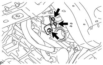
(a) Disconnect the connector. |
|
|
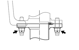
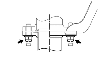
(b) Remove the 2 bolts to separate the front No. 2 exhaust pipe assembly. |
|
|
(c) Remove the 2 nuts to separate the front No. 2 exhaust pipe assembly. |
|
(d) Disconnect the front No. 2 exhaust pipe assembly from the exhaust pipe support.
(e) Remove the 2 gaskets from the front No. 2 exhaust pipe assembly.
7. REMOVE AIR FUEL RATIO SENSOR (for Bank 1 Sensor 1)
8. REMOVE AIR FUEL RATIO SENSOR (for Bank 2 Sensor 1)
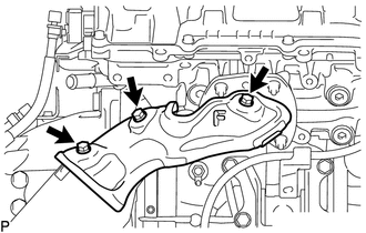
9. REMOVE MANIFOLD STAY
|
(a) Remove the 3 bolts and manifold stay from the transmission assembly and exhaust manifold sub-assembly RH. |
|
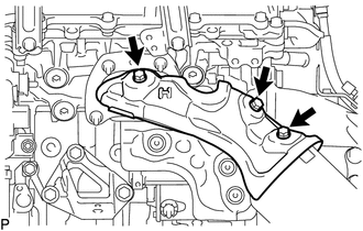
10. REMOVE NO. 1 EXHAUST MANIFOLD HEAT INSULATOR
|
(a) Remove the 3 bolts and No. 1 exhaust manifold heat insulator from the exhaust manifold sub-assembly RH. |
|
11. REMOVE EXHAUST MANIFOLD SUB-ASSEMBLY RH
|
(a) Remove the 4 nuts and exhaust manifold sub-assembly RH from the cylinder head sub-assembly. |
|
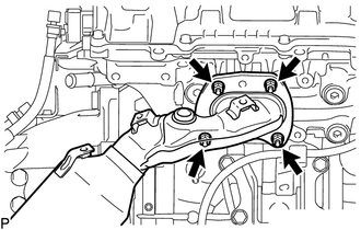
(b) Remove the gasket from the cylinder head sub-assembly.
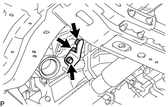
12. REMOVE NO. 2 MANIFOLD STAY
|
(a) Remove the 3 bolts and No. 2 manifold stay from the transmission assembly and exhaust manifold sub-assembly LH. |
|
13. REMOVE NO. 2 EXHAUST MANIFOLD HEAT INSULATOR
|
(a) Remove the 3 bolts and No. 2 exhaust manifold heat insulator from the exhaust manifold sub-assembly LH. |
|
14. REMOVE EXHAUST MANIFOLD SUB-ASSEMBLY LH
|
(a) Remove the 4 nuts and exhaust manifold sub-assembly LH from the cylinder head LH. |
|
(b) Remove the gasket from the cylinder head LH.
 Installation
INSTALLATION
PROCEDURE
1. INSTALL EXHAUST MANIFOLD SUB-ASSEMBLY LH
(a) Install a new gasket to the cylinder head LH.
NOTICE:
Be careful of the installation direction.
(b) Temporarily install the ...
 Exhaust Pipe
...
Other materials:
Terminals Of Ecu
TERMINALS OF ECU
CHECK MILLIMETER WAVE RADAR SENSOR ASSEMBLY
(a) Measure the voltage and resistance according to the value(s) in the table
below.
Terminal No. (Symbol)
Wiring Color
Terminal Description
Condition
Specified Condition
...
Installation
INSTALLATION
PROCEDURE
1. INSTALL TRANSMISSION CONTROL CABLE ASSEMBLY
(a) Install the transmission control cable assembly from outside the vehicle
body and attach the 3 claws of the cable retainer.
(b) Install the 2 nuts.
Torque:
5.5 N·m {56 kgf·cm, 49 in·lbf}
(c) Connect the transmissi ...
Problem Symptoms Table
PROBLEM SYMPTOMS TABLE
If a normal code is displayed during the DTC check but the problem still occurs,
check the circuits for each problem symptom in the order given in the table below
and proceed to the relevant troubleshooting page.
NOTICE:
When replacing the skid control ECU (master cylin ...
