Toyota Tacoma (2015-2018) Service Manual: Removal
REMOVAL
CAUTION / NOTICE / HINT
NOTICE:
If one of the camshaft timing gear bolts is already removed, do not remove any other camshaft timing gear bolts.
PROCEDURE
1. REMOVE NO. 2 ENGINE UNDER COVER SUB-ASSEMBLY (w/ Off Road Package)
2. REMOVE NO. 1 ENGINE UNDER COVER SUB-ASSEMBLY
3. REMOVE CAMSHAFT TIMING OIL CONTROL SOLENOID ASSEMBLY
(See page .gif) )
)
4. SET NO. 1 CYLINDER TO TDC/COMPRESSION
|
(a) Turn the crankshaft clockwise to align the timing mark (cutout) on the crankshaft pulley assembly with the "0" timing mark on the timing chain cover assembly. Text in Illustration
|
|
.png)
|
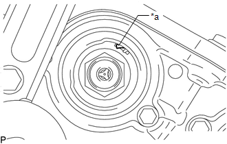
(b) Check that the protrusion on the inside of the camshaft timing gear assembly is at the top. Text in Illustration
HINT: If the protrusion is not at the top, rotate the crankshaft clockwise 360° and align the timing marks again. |
|
5. REMOVE CAMSHAFT TIMING GEAR BOLT
|
(a) Using SST, hold the crankshaft pulley assembly. SST: 09213-54015 91651-60855 SST: 09330-00021 |
|
.png)
|
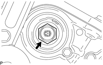
(b) Remove the camshaft timing gear bolt. NOTICE: Replace with a new part if it is dropped or if it receives a strong impact. |
|
 On-vehicle Inspection
ON-VEHICLE INSPECTION
PROCEDURE
1. INSPECT CAMSHAFT TIMING GEAR BOLT
(a) Remove the camshaft timing oil control solenoid assembly (See page
).
(b) Check that the plunger strokes when ...
 Installation
INSTALLATION
PROCEDURE
1. SET NO. 1 CYLINDER TO TDC/COMPRESSION
2. INSTALL CAMSHAFT TIMING GEAR BOLT
NOTICE:
There are different types of camshaft timing gearbolts. Make sure to check the
id ...
Other materials:
Removal
REMOVAL
CAUTION / NOTICE / HINT
HINT:
If the bumper is damaged, there is a possibility that the installation area of
the blind spot monitor sensor may be deformed and the blind spot monitor system
may not operate correctly, so visually inspect the blind spot monitor sensor installation
area ...
Rear Occupant Classification Sensor RH Collision Detection (B1788)
DESCRIPTION
DTC B1788 is set when the occupant detection ECU receives a collision detection
signal, which is sent by the occupant classification sensor rear RH when an accident
occurs.
DTC B1788 is also set when the front seat with adjuster frame assembly RH is
subjected to a strong impact, ...
Navigation Antenna
Components
COMPONENTS
ILLUSTRATION
Installation
INSTALLATION
PROCEDURE
1. INSTALL NAVIGATION ANTENNA ASSEMBLY
(a) Install the navigation antenna assembly with the 2 screws.
(b) Engage the 2 clamps.
2. INSTALL NO. 1 HEATER TO REGISTER DUCT
(See page )
3. INSTALL INSTRUMENT PANEL SUB ...
