Toyota Tacoma (2015-2018) Service Manual: Removal
REMOVAL
PROCEDURE
1. REMOVE NO. 2 ENGINE UNDER COVER SUB-ASSEMBLY (w/ Off Road Package)
2. REMOVE NO. 1 ENGINE UNDER COVER SUB-ASSEMBLY
3. DRAIN ENGINE COOLANT
.gif)
4. REMOVE RADIATOR GRILLE
(See page )
5. REMOVE V-BANK COVER SUB-ASSEMBLY
6. REMOVE RADIATOR SUPPORT TO FRAME SEAL
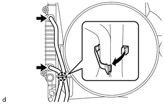
7. REMOVE RADIATOR SIDE DEFLECTOR LH
|
(a) Remove the clip. |
|
(b) Disengage the 3 claws and remove the radiator side deflector LH.
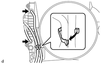
8. REMOVE RADIATOR SIDE DEFLECTOR RH
|
(a) Remove the clip. |
|
(b) Disengage the 3 claws and remove the radiator side deflector RH.
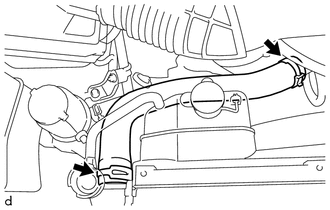
9. REMOVE NO. 1 RADIATOR HOSE
|
(a) Slide the 2 hose clips and remove the No. 1 radiator hose from the water outlet and radiator assembly. |
|
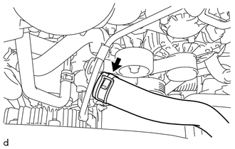
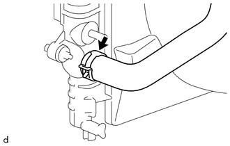
10. REMOVE NO. 2 RADIATOR HOSE
|
(a) Slide the hose clip and disconnect the No. 2 radiator hose from the water inlet with thermostat sub-assembly. |
|
|
(b) Slide the hose clip and remove the No. 2 radiator hose from the radiator assembly. |
|
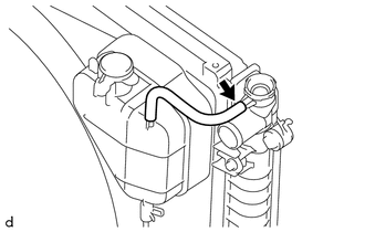
11. DISCONNECT RADIATOR RESERVE TANK HOSE
|
(a) Disconnect the radiator reserve tank hose from the radiator assembly. |
|
12. DISCONNECT TRANSMISSION OIL COOLER HOSE (for Automatic Transmission)
(a) w/o Air Cooled Transmission Oil Cooler:
|
(1) Disengage the clamp to separate the 2 transmission oil cooler hoses from the fan shroud. |
|
(2) Slide the 2 hose clips and disconnect the 2 transmission oil cooler hoses from the radiator assembly.
(b) w/ Air Cooled Transmission Oil Cooler:
|
(1) Disengage the clamp to separate the 2 transmission oil cooler hoses from the fan shroud. |
|
(2) Slide the 2 hose clips and disconnect the 2 transmission oil cooler hoses from the radiator assembly.
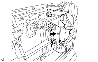
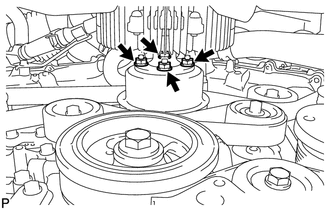
13. REMOVE FAN SHROUD
|
(a) Loosen the 4 nuts holding the fan with fluid coupling. |
|
(b) Remove the fan and generator V belt (See page
).
|
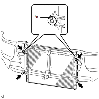
(c) Remove the 2 bolts holding the fan shroud. |
|
(d) Remove the 4 nuts of the fan with fluid coupling, and then remove the fan shroud together with the fan with fluid coupling.
NOTICE:
Be careful not to damage the radiator core.
(e) Remove the fan pulley from the engine water pump assembly.
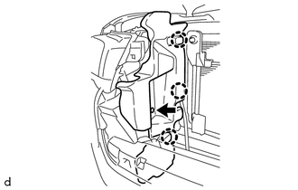
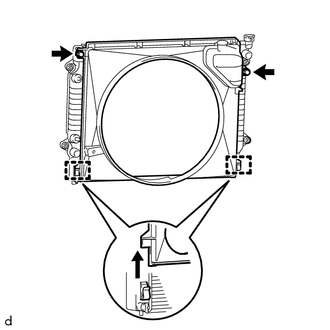
14. REMOVE RADIATOR ASSEMBLY
|
(a) Remove the 4 bolts. Text in Illustration
|
|
(b) Disengage the 2 hooks and remove the radiator assembly from the radiator support sub-assembly.
 Disassembly
DISASSEMBLY
PROCEDURE
1. REMOVE RADIATOR DRAIN COCK PLUG
(a) Remove the radiator drain cock plug from the radiator assembly.
(b) Remove the O-ring from the radiator drain cock plug.
2. REMOVE RAD ...
 Inspection
INSPECTION
PROCEDURE
1. INSPECT RADIATOR CORE SUB-ASSEMBLY
Check the core plate for damage.
Text in Illustration
*1
Core Plate
*2
Radiator Core
...
Other materials:
Four-wheel drive system
Use the front-wheel drive control switch to select the following transfer modes.
H2 (high speed position, two-wheel
drive)
Use this for normal driving on dry hard-surfaced roads.
This position gives greater economy, quietest ride and least wear.
H4 (high speed position, four-wheel
drive) ...
Removal
REMOVAL
PROCEDURE
1. REMOVE AUTOMATIC TRANSMISSION ASSEMBLY (for Automatic Transmission)
Transmission
See page
AC60E
AC60F
2. REMOVE MANUAL TRANSMISSION ASSEMBLY (for Manual Transmission)
(See page )
...
Clutch Switch Circuit
DESCRIPTION
Clutch switch circuit inspection is necessary for manual transmission vehicles.
When the clutch pedal is released, the ECM receives the positive (+) battery
voltage through the ECU-IG NO. 2 fuse and ignition switch. While the clutch pedal
is depressed, the clutch switch assembly se ...
