Toyota Tacoma (2015-2018) Service Manual: Disassembly
DISASSEMBLY
PROCEDURE
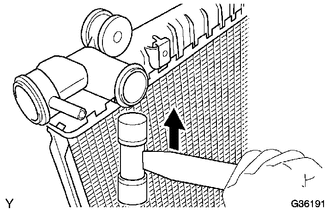
1. REMOVE RADIATOR DRAIN COCK PLUG
(a) Remove the radiator drain cock plug from the radiator assembly.
(b) Remove the O-ring from the radiator drain cock plug.
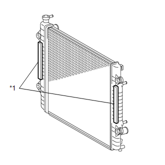
2. REMOVE RADIATOR TO SUPPORT SEAL
|
(a) Remove the 2 radiator to support seals from the radiator assembly. Text in Illustration
|
|
3. REMOVE RADIATOR SUPPORT BUSHING
|
(a) Remove the 2 No. 1 radiator support collars and 2 No. 1 radiator support bushings from the radiator assembly. Text in Illustration
|
|
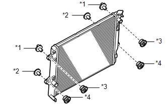
(b) Remove the 2 No. 2 radiator support collars and 2 No. 2 radiator support bushings from the radiator assembly.
4. ASSEMBLE SST
|
(a) Engage the claw with the overhaul handle by inserting it into the hole in part A as shown in the illustration. Text in Illustration
SST: 09230-01010 09231-01010 09231-01030 |
|
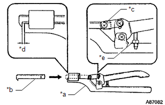
(b) While gripping the handle, adjust dimension B to between 0.2 and 0.3 mm (0.00787 and 0.0118 in.), using the stopper bolt.
Dimension B:
0.2 to 0.3 mm (0.00787 to 0.0118 in.)
NOTICE:
If the stopper bolt cannot be adjusted, the claw may be damaged.
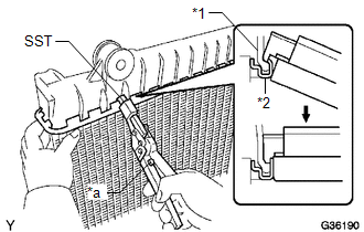
5. UNCAULK CORE PLATE
|
(a) Straighten the core plate by gripping it with SST until stopped by the stopper bolt. Text in Illustration
SST: 09230-01010 09231-01010 09231-01030 |
|
6. REMOVE UPPER RADIATOR TANK
|
(a) Lightly tap the radiator tank bracket (or radiator tank pipe) with a plastic hammer to remove the upper radiator tank. |
|
7. REMOVE LOWER RADIATOR TANK
HINT:
Perform the same procedures as for the upper radiator tank.
 On-vehicle Inspection
ON-VEHICLE INSPECTION
PROCEDURE
1. INSPECT RADIATOR CAP SUB-ASSEMBLY
CAUTION:
Do not remove the radiator cap sub-assembly while the engine and radiator assembly
are still hot. Pressurized, hot e ...
 Removal
REMOVAL
PROCEDURE
1. REMOVE NO. 2 ENGINE UNDER COVER SUB-ASSEMBLY (w/ Off Road Package)
2. REMOVE NO. 1 ENGINE UNDER COVER SUB-ASSEMBLY
3. DRAIN ENGINE COOLANT
4. REMOVE RADIATOR GRILLE
(See ...
Other materials:
Reassembly
REASSEMBLY
PROCEDURE
1. INSTALL FRONT BUMPER COVER INSERT LH
(a) Engage the clip to install the front bumper cover insert LH.
(b) Install the bolt.
Torque:
5.9 N·m {60 kgf·cm, 52 in·lbf}
2. INSTALL FRONT BUMPER COVER INSERT RH
HINT:
U ...
Installation
INSTALLATION
PROCEDURE
1. INSTALL AIR CONDITIONING UNIT ASSEMBLY
(a) Temporary install the air conditioning unit assembly.
(b) Insert the bracket hook into the holes of the reinforcement bracket, and
temporary install the instrument panel reinforcement assembly.
(c) Install the instrument p ...
Data List / Active Test
DATA LIST / ACTIVE TEST
1. DATA LIST
NOTICE:
In the table below, the values listed under "Normal Condition" are reference
values. Do not depend solely on these reference values when deciding whether a part
is faulty or not.
HINT:
Using the Techstream to read the Data List allows t ...
