Toyota Tacoma (2015-2018) Service Manual: Accelerator Pedal
Components
COMPONENTS
ILLUSTRATION
On-vehicle Inspection
ON-VEHICLE INSPECTION
PROCEDURE
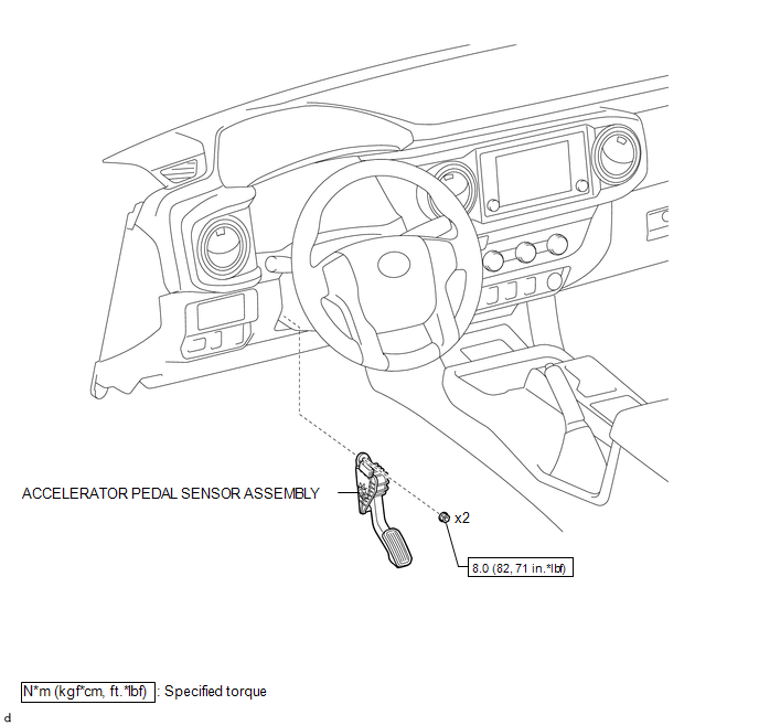
1. INSPECT ACCELERATOR PEDAL SENSOR ASSEMBLY
(a) Connect the Techstream to the DLC3.
(b) Turn the ignition switch to ON.
(c) Turn the Techstream on.
(d) Enter the following menus: Powertrain / Engine / Data List / Accelerator Position Sensor No. 1 Voltage and Accelerator Position Sensor No. 2 Voltage.
(e) When depressing or releasing the accelerator pedal, check that the values of Accelerator Position Sensor No. 1 Voltage and Accelerator Position Sensor No. 2 Voltage are within the specification.
Standard Voltage:
|
Item |
Condition |
Specified Condition |
|---|---|---|
|
Accelerator Position Sensor No. 1 Voltage |
Released |
0.5 to 1.1 V |
|
Depressed |
2.6 to 4.5 V |
|
|
Accelerator Position Sensor No. 2 Voltage |
Released |
1.2 to 2.0 V |
|
Depressed |
3.4 to 4.75 V |
If the result is not as specified, check the accelerator pedal sensor assembly, wire harness and ECM.
Installation
INSTALLATION
PROCEDURE
1. INSTALL ACCELERATOR PEDAL SENSOR ASSEMBLY
NOTICE:
This accelerator pedal sensor assembly does not require lubrication. Do not apply oil or other lubrication to the accelerator pedal sensor assembly. If applied, the accelerator pedal sensor assembly must be replaced.
(a) Install the accelerator pedal sensor assembly to the vehicle body with the 2 bolts.
Torque:
8.0 N·m {82 kgf·cm, 71 in·lbf}
NOTICE:
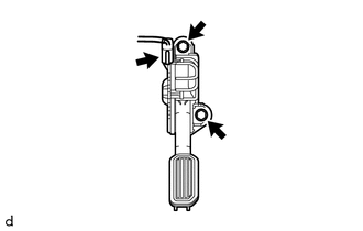
- Avoid any physical impact to the accelerator pedal sensor assembly.
- Do not disassemble the accelerator pedal sensor assembly.
(b) Connect the connector to the accelerator pedal sensor assembly.
Removal
REMOVAL
PROCEDURE
1. REMOVE ACCELERATOR PEDAL SENSOR ASSEMBLY
NOTICE:
This accelerator pedal sensor assembly does not require lubrication. Do not apply oil or other lubrication to the accelerator pedal sensor assembly. If applied, the accelerator pedal sensor assembly must be replaced.
|
(a) Disconnect the connector from the accelerator pedal sensor assembly. |
|
(b) Remove the 2 bolts and accelerator pedal sensor assembly from the vehicle body.

 Air Fuel Ratio Sensor
Components
COMPONENTS
ILLUSTRATION
Removal
REMOVAL
PROCEDURE
1. REMOVE AIR FUEL RATIO SENSOR (for Bank 1 Sensor 1)
(a) Disconnect the air fuel ratio sensor connector.
...
Other materials:
How To Proceed With Troubleshooting
CAUTION / NOTICE / HINT
HINT:
Use these procedures to troubleshoot the lane departure alert system.
*: Use the Techstream.
PROCEDURE
1.
VEHICLE BROUGHT TO WORKSHOP
NEXT
...
Detecting Vehicle Submersion (B2277)
DESCRIPTION
This DTC is stored when a malfunction in the water submersion detection circuit
in the certification ECU (smart key ECU assembly) is detected.
HINT:
When the cable is disconnected and reconnected to the negative (-) battery terminal,
the power source mode returns to the state it w ...
Pressure Control Solenoid "C" Actuator Stuck Off (P07957F)
SYSTEM DESCRIPTION
The ECM uses the vehicle speed signal and signals from the transmission revolution
sensors (NT, SP2) to detect the actual gear (1st, 2nd, 3rd, 4th, 5th or 6th gear).
The ECM compares the actual gear with the shift schedule in the ECM memory to
detect mechanical problems of t ...
