Toyota Tacoma (2015-2018) Service Manual: Removal
REMOVAL
PROCEDURE
1. PRECAUTION
NOTICE:
After turning the ignition switch off, waiting time may be required before disconnecting the cable from the negative (-) battery terminal.
Therefore, make sure to read the disconnecting the cable from the negative (-) battery terminal notices before proceeding with work.
Click here .gif)
2. DISCONNECT CABLE FROM NEGATIVE BATTERY TERMINAL
NOTICE:
When disconnecting the cable, some systems need to be initialized after the cable is reconnected.
Click here
3. DRAIN BRAKE FLUID
NOTICE:
Immediately wash off any brake fluid that comes into contact with any painted surfaces.
4. REMOVE AIR CLEANER CAP SUB-ASSEMBLY (for 2TR-FE)
Click here
5. REMOVE AIR CLEANER FILTER ELEMENT SUB-ASSEMBLY (for 2TR-FE)
6. REMOVE AIR CLEANER CASE SUB-ASSEMBLY (for 2TR-FE)
Click here
7. REMOVE BRAKE ACTUATOR ASSEMBLY
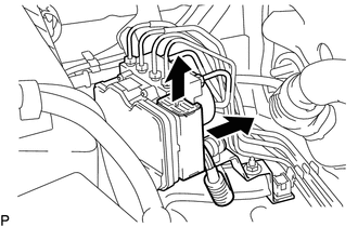
(a) Release the connector lock lever.
(b) Disconnect the brake actuator connector.
|
(c) Using a union nut wrench, separate the 6 brake tubes from the brake actuator. |
|
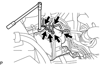
|
(d) Use tags or labels to identify the place to reconnect each brake tube. Text in Illustration
|
|
.png)
|
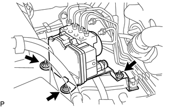
(e) Remove the 3 nuts and brake actuator with bracket. |
|
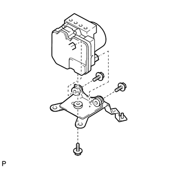
8. REMOVE BRAKE ACTUATOR BRACKET ASSEMBLY
|
(a) Remove the 3 bolts and actuator bracket. |
|
 Installation
INSTALLATION
PROCEDURE
1. INSTALL BRAKE ACTUATOR BRACKET ASSEMBLY
(a) Install the actuator bracket with the 3 bolts in the sequence shown
in the illustration.
Torque:
5.4 N·m ...
 Crawl Switch
Components
COMPONENTS
ILLUSTRATION
Inspection
INSPECTION
PROCEDURE
1. INSPECT CRAWL CONTROL SWITCH (DRIVE MONITOR SWITCH)
(a) Check the resistance.
(1) Measure the resistance according t ...
Other materials:
Components
COMPONENTS
ILLUSTRATION
*1
FRONT FENDER LINER
*2
FRONT NO.1 WHEEL OPENING EXTENSION PAD
*3
FOG LIGHT UNIT
-
-
...
Problem Symptoms Table
PROBLEM SYMPTOMS TABLE
NOTICE:
Before replacing the ECM, refer to Registration.
w/o Smart Key System: Click here
w/ Smart Key System: Click here
When the millimeter wave radar sensor assembly is replaced with a new
one, adjustment of the radar sensor beam axis must be ...
Side doors
The vehicle can be locked/unlocked using the wireless remote control, key or
door lock switch.
■ Wireless remote control (if equipped)
■ Key
Regular Cab models
Locks the door
Unlocks the door
Access Cab and Double Cab models
Locks all doors
Unlocks all doors
Turning ...
