Toyota Tacoma (2015-2018) Service Manual: Installation
INSTALLATION
PROCEDURE
1. INSTALL BRAKE ACTUATOR BRACKET ASSEMBLY
|
(a) Install the actuator bracket with the 3 bolts in the sequence shown in the illustration. Torque: 5.4 N·m {55 kgf·cm, 48 in·lbf} |
|
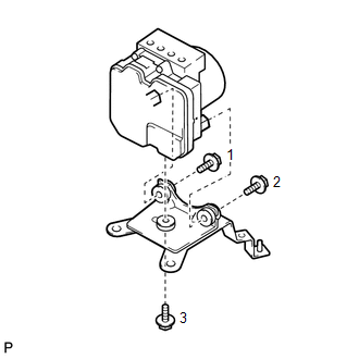
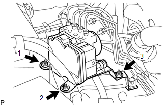
2. INSTALL BRAKE ACTUATOR ASSEMBLY
|
(a) Install the brake actuator with bracket with the 3 nuts in the sequence shown in the illustration. Torque: 19 N·m {194 kgf·cm, 14 ft·lbf} NOTICE:
|
|
|
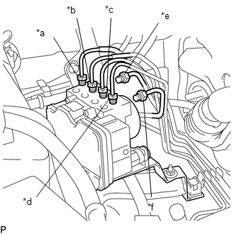
(b) Temporarily install each brake tube in the correct positions of the brake actuator as shown in the illustration. Text in Illustration
|
|
|
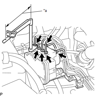
(c) Using a union nut wrench, install the 6 brake tubes to the brake actuator. Text in Illustration
(1) for 12 mm flare nuts : Torque: Specified tightening torque : 20 N·m {199 kgf·cm, 14 ft·lbf} HINT:
(2) for 10 mm flare nuts : Torque: Specified tightening torque : 15 N·m {155 kgf·cm, 11 ft·lbf} HINT:
|
|
(d) Connect the brake actuator connector.
(e) Lock the connector lock lever.
NOTICE:
Make sure that the lever is locked securely.
3. INSTALL AIR CLEANER CASE SUB-ASSEMBLY (for 2TR-FE)
Click here .gif)
4. INSTALL AIR CLEANER FILTER ELEMENT SUB-ASSEMBLY (for 2TR-FE)
5. INSTALL AIR CLEANER CAP SUB-ASSEMBLY (for 2TR-FE)
Click here
6. CONNECT CABLE TO NEGATIVE BATTERY TERMINAL
Torque:
5.4 N·m {55 kgf·cm, 48 in·lbf}
NOTICE:
When disconnecting the cable, some systems need to be initialized after the cable is reconnected.
Click here
7. FILL RESERVOIR WITH BRAKE FLUID
Click here
8. BLEED MASTER CYLINDER
Click here
9. BLEED BRAKE LINE
Click here
10. BLEED BRAKE ACTUATOR
Click here
11. INSPECT FLUID LEVEL IN RESERVOIR
Click here
12. INSPECT FOR BRAKE FLUID LEAK
13. CHECK BRAKE ACTUATOR WITH TECHSTREAM
Click here
14. PERFORM YAW RATE AND ACCELERATION SENSOR ZERO POINT CALIBRATION
Click here
15. CHECK AND CLEAR DTC
Click here
 On-vehicle Inspection
ON-VEHICLE INSPECTION
PROCEDURE
1. CONNECT TECHSTREAM
(a) Warm up the engine.
(b) Turn the ignition switch to off.
(c) Connect the Techstream to the DLC3.
(d) Turn the ignition switch to ON.
(e ...
 Removal
REMOVAL
PROCEDURE
1. PRECAUTION
NOTICE:
After turning the ignition switch off, waiting time may be required before disconnecting
the cable from the negative (-) battery terminal.
Therefore, mak ...
Other materials:
Dtc Check / Clear
DTC CHECK / CLEAR
1. CHECK DTC
(a) Connect the Techstream to the DLC3.
(b) Turn the ignition switch to ON.
(c) Turn the Techstream on.
(d) Enter the following menus: Body Electrical / Sliding Roof / Trouble Codes.
(e) Check the details of the DTC(s) (See page
).
2. CLEAR DTC
(a) Connect th ...
System Diagram
SYSTEM DIAGRAM
Communication Table
Transmitting ECU
Receiving ECU
Signal
Communication Method
Power Window Regulator Master Switch Assembly
Power Window Regulator Motor Assembly (for Driver Door)
Power Window ...
Calibration
CALIBRATION
1. DESCRIPTION
(a) After replacing any VSC related components or performing wheel alignment
adjustment, clear and read the sensor calibration data.
Refer to the table below and then perform the necessary operation according to
the part to be replaced in order to perform calibratio ...
