Toyota Tacoma (2015-2018) Service Manual: Removal
REMOVAL
PROCEDURE
1. REMOVE LOWER STEERING COLUMN COVER
.gif)
2. REMOVE UPPER STEERING COLUMN COVER
3. REMOVE WINDSHIELD WIPER SWITCH ASSEMBLY
|
(a) Disconnect the 2 connectors. Text in Illustration
|
|
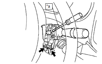
(b) Using a screwdriver with its tip wrapped in protective tape, disengage the claw to remove the windshield wiper switch assembly.
NOTICE:
If the claw is pulled with excessive force, it may break.
 On-vehicle Inspection
ON-VEHICLE INSPECTION
PROCEDURE
1. INSPECT WINDSHIELD WIPER SWITCH ASSEMBLY (w/ Intermittent function)
(a) Remove the steering column cover.
(b) Check the front wiper intermittent operation.
Tex ...
 Inspection
INSPECTION
PROCEDURE
1. INSPECT WINDSHIELD WIPER SWITCH ASSEMBLY
(a) Check the resistance.
Text in Illustration
*a
Component without harness conne ...
Other materials:
Disassembly
DISASSEMBLY
PROCEDURE
1. REMOVE TAIL GATE PROTECTOR
(See page )
2. REMOVE TAIL GATE SERVICE HOLE COVER
(a) Using a T30 "TORX" socket wrench, remove the 8 screws and tail gate
service hole cover.
3. REMOVE REAR TELEVISION CAMER ...
Rear Airbag Sensor RH Circuit Malfunction (B1630/23)
DESCRIPTION
The airbag sensor RH consists of parts such as the safing sensor, the diagnostic
circuit and the lateral deceleration sensor.
When the airbag sensor assembly receives signals from the lateral deceleration
sensor, it determines whether or not the SRS should be activated.
DTC B1630/ ...
Registration
REGISTRATION
PROCEDURE
1. REGISTER TRANSMITTER CODE
HINT:
The vehicle's garage door opener records transmitter codes for systems
such as garage doors, gates, entry gates, door locks, home lighting systems,
security systems or other transmitter code based systems.
The gara ...
