Toyota Tacoma (2015-2018) Service Manual: Pressure Control Solenoid "D" Electrical (Shift Solenoid Valve SLT) (P2716)
DESCRIPTION
Refer to the system description for DTC P2714 (See page
.gif) ).
).
|
DTC No. |
DTC Detection Condition |
Trouble Area |
|---|---|---|
|
P2716 |
Open or short is detected in shift solenoid valve SLT circuit for 1 second or more while driving (1 trip detection logic). |
|
MONITOR DESCRIPTION
When an open or short in the shift solenoid valve SLT circuit is detected, the ECM interprets this as a fault. The ECM will illuminate the MIL and store the DTC.
MONITOR STRATEGY
|
Related DTCs |
P2716: Shift solenoid valve SLT/Range check |
|
Required sensors/Components |
Shift solenoid valve SLT |
|
Frequency of operation |
Continuous |
|
Duration |
1 sec. |
|
MIL operation |
Immediately |
|
Sequence of operation |
None |
TYPICAL ENABLING CONDITIONS
All:|
The monitor will run whenever the following DTCs are not stored |
None |
|
Solenoid current cut status |
Not cut |
|
Ignition switch |
ON |
|
Starter |
OFF |
|
Battery voltage |
12 V or higher |
|
Battery voltage |
10 V or higher, and below 12 V |
|
Target current |
Below 0.75 A |
|
Battery voltage |
8 V or higher |
|
Target current |
0.25 A or higher |
|
Battery voltage |
11 V or higher |
|
Target current |
1 A or higher |
|
Battery voltage |
11 V or higher |
|
Target current |
0.1 A or more |
|
l Target voltage - Last Target voltage l |
Less than 0.000019 V |
TYPICAL MALFUNCTION THRESHOLDS
One of the following conditions is met: Condition (A), (B), (C) or (D)
Condition (A) and (B):|
Output duty cycle |
100% or more |
|
Output duty cycle |
0% or less |
|
Solenoid voltage monitor |
No signal |
|
l Target voltage - Average of monitor voltage l |
0.035 V or more |
COMPONENT OPERATING RANGE
|
Output duty cycle |
More than 3%, and less than 100% |
|
Solenoid voltage monitor |
Signal input |
|
l Target voltage - Average of monitor voltage l |
Less than 0.035 V |
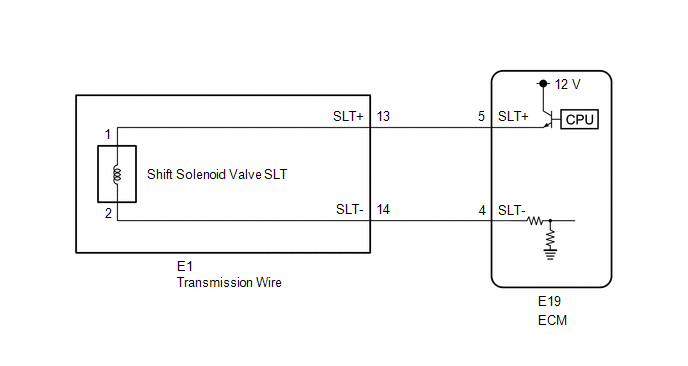
WIRING DIAGRAM
CAUTION / NOTICE / HINT
NOTICE:
- Perform the universal trip to clear permanent DTCs (See page
).
- Perform registration and/or initialization when parts related to the
automatic transmission are replaced (See page
).
HINT:
After the repair, clear the DTCs and perform the following procedure to check that DTCs are not output.
- Start the engine.
- Check for DTCs again (See page ).
PROCEDURE
|
1. |
INSPECT TRANSMISSION WIRE (SHIFT SOLENOID VALVE SLT) |
|
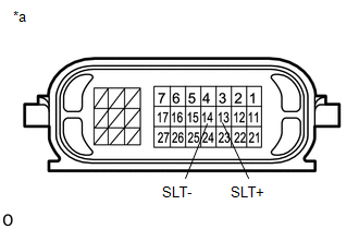
(a) Disconnect the E1 transmission wire connector. |
|
(b) Measure the resistance according to the value(s) in the table below.
Standard Resistance:
|
Tester Connection |
Condition |
Specified Condition |
|---|---|---|
|
13 (SLT+) - 14 (SLT-) |
20°C (68°F) |
5.0 to 5.6 Ω |
|
13 (SLT+) - Body ground |
Always |
10 kΩ or higher |
|
14 (SLT-) - Body ground |
Always |
10 kΩ or higher |
|
*a |
Component without harness connected (Transmission Wire) |
| NG | .gif) |
GO TO STEP 3 |
|
.gif)
|
2. |
CHECK HARNESS AND CONNECTOR (TRANSMISSION WIRE - ECM) |
|
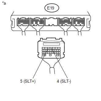
(a) Disconnect the ECM connector. |
|
(b) Measure the resistance according to the value(s) in the table below.
Standard Resistance:
|
Tester Connection |
Condition |
Specified Condition |
|---|---|---|
|
E19-5 (SLT+) - E19-4 (SLT-) |
20°C (68°F) |
5.0 to 5.6 Ω |
|
E19-5 (SLT+) - Body ground |
Always |
10 kΩ or higher |
|
E19-4 (SLT-) - Body ground |
Always |
10 kΩ or higher |
|
*a |
Rear view of wire harness connector (to ECM) |
| OK | |
REPLACE ECM |
| NG | |
REPAIR OR REPLACE HARNESS OR CONNECTOR |
|
3. |
INSPECT SHIFT SOLENOID VALVE SLT |
|
(a) Remove shift solenoid valve SLT (See page
|
|
.png)
(b) Measure the resistance according to the value(s) in the table below.
Standard Resistance:
|
Tester Connection |
Condition |
Specified Condition |
|---|---|---|
|
1 - 2 |
20°C (68°F) |
5.0 to 5.6 Ω |
(c) Apply 12 V battery voltage to the shift solenoid valve and check that the valve moves and makes an operating noise.
OK:
|
Measurement Condition |
Specified Condition |
|---|---|
|
Valve moves and makes an operating noise |
|
*1 |
Shift Solenoid Valve SLT |
| OK | |
REPLACE TRANSMISSION WIRE |
| NG | |
REPLACE SHIFT SOLENOID VALVE SLT |
 Vehicle Control History
VEHICLE CONTROL HISTORY
VEHICLE CONTROL HISTORY
(a) A part of the control history can be confirmed using the vehicle control
history.
Click here ...
 Transmission Fluid Temperature Sensor "B" Circuit Low Input (P2742,P2743)
DESCRIPTION
The No. 2 ATF temperature sensor is installed in the transmission valve body
assembly.
If the ECM detects an abnormally high ATF temperature near this sensor, it illuminates
the warn ...
Other materials:
Check For Intermittent Problems
CHECK FOR INTERMITTENT PROBLEMS
1. DESCRIPTION
HINT:
A momentary interruption (open circuit) in the connectors and/or wire harness
between the sensors and ECUs can be detected through the ECU data monitor function
of the Techstream.
(a) Turn the ignition switch off.
(b) Connect the Techstre ...
Entune Audio
Operations such as listening to audio, using the hands-free phone, confirming
vehicle information and changing multimedia system settings are started by using
the following buttons.
Multimedia system operation buttons
button
Press this button to access the Bluetooth® hands-free system.
...
Components
COMPONENTS
ILLUSTRATION
ILLUSTRATION
ILLUSTRATION
ILLUSTRATION
...
