Toyota Tacoma (2015-2018) Service Manual: Removal
REMOVAL
CAUTION / NOTICE / HINT
CAUTION:
Some of these service operations affect the SRS airbag system. Read the precautionary
notices concerning the SRS airbag system before servicing (See page
.gif) ).
).
HINT:
- Use the same procedure for the LH side and RH side.
- The procedure listed below is the LH side.
PROCEDURE
1. PRECAUTION
CAUTION:
Be sure to read Precaution thoroughly before servicing (See page
).
NOTICE:
After turning the ignition switch off, waiting time may be required before disconnecting the cable from the negative (-) battery terminal. Therefore, make sure to read the disconnecting the cable from the negative (-) battery terminal notices before proceeding with work.
Click here
2. DISCONNECT CABLE FROM NEGATIVE BATTERY TERMINAL
CAUTION:
Wait at least 90 seconds after disconnecting the cable from the negative (-) battery terminal to disable the SRS system.
NOTICE:
When disconnecting the cable, some systems need to be initialized after the cable is reconnected.
Click here
3. REMOVE REAR SEAT 3 POINT TYPE OUTER BELT ASSEMBLY
Click here
4. REMOVE REAR AIRBAG SENSOR
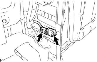
(a) Disconnect the connector from the rear airbag sensor.
NOTICE:
When disconnecting any airbag connector, take care not to damage the airbag wire harness.
(1) Push and hold the white housing lock, and slide the yellow outer connector locking sleeve.
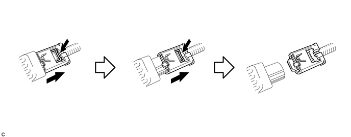
(2) Push and hold the white housing lock again, and slide the yellow outer connector locking sleeve to disconnect the connector.
(b) Remove the nut and the rear airbag sensor LH.
NOTICE:
Loosen the nut while holding the door side airbag sensor because the rear airbag sensor pin (stopper) is easily damaged.
 On-vehicle Inspection
ON-VEHICLE INSPECTION
PROCEDURE
1. INSPECT REAR AIRBAG SENSOR (for Vehicle not Involved in Collision)
(a) Perform a diagnostic system check (See page
).
2. INSPECT REAR AIRBAG SENSOR (for Vehicl ...

Other materials:
Operation Check
OPERATION CHECK
1. CHECK WIRELESS CHARGING SYSTEM OPERATION
(a) Turn the ignition switch ON (IG or ACC).
(b) Press the mobile wireless charger switch and check that the switch indicator
light illuminates.
Text in Illustration
*a
Switch Indicator Light
(c) Plac ...
Blind Spot Monitor Slave Module (C1AB7)
DESCRIPTION
This DTC is stored when the blind spot monitor sensor RH detects an internal
malfunction.
DTC Code
DTC Detection Condition
Trouble Area
C1AB7
The blind spot monitor sensor RH (slave) detects an internal malfunction.
...
Brake Control Signal Mismatch (C1A69)
DESCRIPTION
The skid control ECU (master cylinder solenoid)*1 or skid control ECU (brake
actuator assembly)*2 sends signals to the millimeter wave radar sensor assembly
according to the brake control status. If the millimeter wave radar sensor assembly
receives a vehicle stability control sys ...
