Toyota Tacoma (2015-2018) Service Manual: Removal
REMOVAL
CAUTION / NOTICE / HINT
HINT:
- Use the same procedure for both the RH and LH sides.
- The procedure described below is for the LH side.
PROCEDURE
1. PRECAUTION
NOTICE:
After turning the ignition switch off, waiting time may be required before disconnecting the cable from the negative (-) battery terminal. Therefore, make sure to read the disconnecting the cable from the negative (-) battery terminal notices before proceeding with work.
Click here .gif)
2. DISCONNECT CABLE FROM NEGATIVE BATTERY TERMINAL
CAUTION:
Wait at least 90 seconds after disconnecting the cable from the negative (-) battery terminal to disable the SRS system.
NOTICE:
When disconnecting the cable, some systems need to be initialized after the cable is reconnected.
Click here
3. REMOVE ACCESS PANEL REAR WEATHERSTRIP
Click here
4. REMOVE LAP BELT OUTER ANCHOR COVER
Click here
5. REMOVE ACCESS PANEL INSIDE HANDLE BEZEL
Click here
6. REMOVE DOOR PULL HANDLE
Click here
7. REMOVE REAR DOOR TRIM BOARD SUB-ASSEMBLY
Click here
8. REMOVE ACCESS PANEL INSIDE HANDLE SUB-ASSEMBLY
Click here
9. REMOVE FRONT SEAT OUTER BELT ASSEMBLY
|
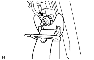
(a) Remove the nut to disconnect the shoulder anchor. |
|
|
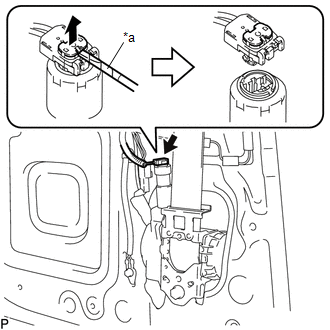
(b) Using a screwdriver with its tip wrapped in protective tape, release the locking button to disconnect the connector. Text in Illustration
|
|
|
(c) Remove the 2 bolts. |
|
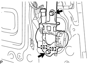
(d) Disengage the 2 guides to remove the front seat outer belt assembly.
10. REMOVE FRONT SHOULDER BELT ANCHOR ADJUSTER ASSEMBLY
|
(a) Remove the bolt. |
|
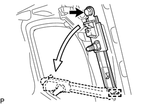
(b) Disengage the guide to remove the front shoulder belt anchor adjuster assembly as shown in the illustration.
 Installation
INSTALLATION
CAUTION / NOTICE / HINT
HINT:
Use the same procedure for both the RH and LH sides.
The procedure described below is for the LH side.
PROCEDURE
1. INSTALL FRONT SHOU ...

Other materials:
Front Passenger Side Power Window Auto Up / Down Function does not Operate with
Front Passenger Side Power Window Switch
DESCRIPTION
If the manual up/down function can be performed but the auto up/down function
cannot, the fail-safe mode may be functioning.
If the power window initialization (See page
) has not been performed, the auto up/down function will not operate.
WIRING DIAGRAM
CAUTION / NOTICE / HIN ...
Installation
INSTALLATION
PROCEDURE
1. INSTALL TRANSFER POSITION SWITCH (for 4WD)
Click here
2. INSTALL ENGINE SWITCH
Click here
3. INSTALL AIR CONDITIONING CONTROL ASSEMBLY
(a) Connect the connectors.
(b) Engage the 8 clips to install the air conditioning control assembly.
4. INSTALL RADIO AND DISP ...
Inspection
INSPECTION
PROCEDURE
1. INSPECT HAZARD WARNING SIGNAL SWITCH ASSEMBLY (AIR CONDITIONING CONTROL ASSEMBLY)
(a) Check the resistance.
(1) Measure the resistance according to the value(s) in the table below.
Text in Illustration
*a
Component withou ...
