Toyota Tacoma (2015-2018) Service Manual: Removal
REMOVAL
CAUTION / NOTICE / HINT
HINT:
- Use the same procedure for both the LH and RH sides.
- The procedure described below is for the LH side.
PROCEDURE
1. REMOVE FRONT BUMPER ASSEMBLY
(See page .gif) )
)
2. REMOVE HEADLIGHT ASSEMBLY
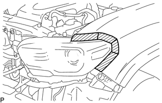
(a) Apply protective tape around the headlight assembly.
 Text in Illustration
.png) |
Protective Tape |
|
(b) Remove the bolt and 2 screws. |
|
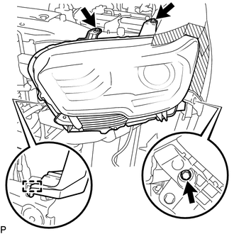
(c) Disengage the clamp to separate the headlight assembly.
(d) Disconnect the connectors to remove the headlight assembly.
 Disassembly
DISASSEMBLY
CAUTION / NOTICE / HINT
HINT:
Use the same procedure for both the LH and RH sides.
The procedure described below is for the LH side.
PROCEDURE
1. REMOVE NO. 1 HEADLI ...
 Adjustment
ADJUSTMENT
PROCEDURE
1. PREPARE VEHICLE FOR HEADLIGHT AIM ADJUSTMENT
(a) Prepare the vehicle:
Ensure that there is no damage or deformation to the body around the
headlights.
Fill t ...
Other materials:
Installation
INSTALLATION
PROCEDURE
1. INSTALL POWER STEERING LINK
(a) Insert the power steering link into the vehicle in the order shown in the
illustration.
Install in this Direction (1)
Install in this Direction (2)
(b) Using SST, inst ...
Power Source Circuit
DESCRIPTION
This circuit provides power to operate the forward recognition camera.
WIRING DIAGRAM
CAUTION / NOTICE / HINT
NOTICE:
Inspect the fuses for circuits related to this system before performing the following
inspection procedure.
PROCEDURE
1.
CHECK HARNESS A ...
If a warning light turns on or a warning buzzer sounds
Calmly perform the following actions if any of the warning lights turn on
or flash. If a light turns on or flashes, but then turns off, this does not necessarily
indicate a malfunction in the system.
Stop the vehicle immediately. Continuing to drive the vehicle may be dangerous.
The following ...
