Toyota Tacoma (2015-2018) Service Manual: Disassembly
DISASSEMBLY
CAUTION / NOTICE / HINT
HINT:
- Use the same procedure for both the LH and RH sides.
- The procedure described below is for the LH side.
PROCEDURE
1. REMOVE NO. 1 HEADLIGHT BULB
|
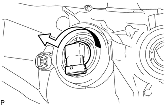
(a) Turn the No. 1 headlight bulb in the direction indicated by the arrow in the illustration to remove it. NOTICE: Do not touch the No. 1 headlight bulb glass. |
|
2. REMOVE NO. 2 HEADLIGHT BULB
|
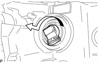
(a) Turn the No. 2 headlight bulb in the direction indicated by the arrow in the illustration to remove it. NOTICE: Do not touch the No. 2 headlight bulb glass. |
|
3. REMOVE FRONT TURN SIGNAL LIGHT BULB
|
(a) Turn the front turn signal light socket with front turn signal light bulb in the direction indicated by the arrow shown in the illustration to remove them. |
|
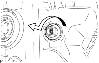
(b) Remove the front turn signal light bulb from the front turn signal light socket.
4. REMOVE CLEARANCE LIGHT BULB
|
(a) Turn the clearance light socket with clearance light bulb in the direction indicated by the arrow shown in the illustration to remove them. |
|
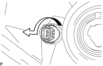
(b) Remove the clearance light bulb from the clearance light socket.
 Components
COMPONENTS
ILLUSTRATION
ILLUSTRATION
...
 Removal
REMOVAL
CAUTION / NOTICE / HINT
HINT:
Use the same procedure for both the LH and RH sides.
The procedure described below is for the LH side.
PROCEDURE
1. REMOVE FRONT BUMPER ASS ...
Other materials:
Fail-safe Chart
FAIL-SAFE CHART
FAIL-SAFE FUNCTION
(a) When a malfunction occurs in the lane departure alert system, a message will
be displayed on the multi-information display in the combination meter assembly
and the lane departure alert system will be disabled depending on the malfunction.
War ...
Reassembly
REASSEMBLY
PROCEDURE
1. INSTALL SHIFT SOLENOID VALVE SLT
(a) Install the shift solenoid valve SLT and straight pin to the transmission
valve body assembly.
2. INSTALL SHIFT SOLENOID VALVE SL2
(a) Install the shift solenoid valv ...
Rear Left Sensor Malfunction (C1AE6)
DESCRIPTION
The No. 1 ultrasonic sensor (rear corner sensor LH) is installed on the rear
bumper. The ECU detects obstacles based on signals received from the No. 1 ultrasonic
sensor (rear corner sensor LH). If the No. 1 ultrasonic sensor (rear corner sensor
LH) has an open circuit or other ma ...
